VEHICLE STABILITY CONTROL SYSTEM (for Vacuum Brake Booster), Diagnostic DTC:C1282

| DTC Code | DTC Name |
|---|---|
| C1282 | Center Differential Lock Position Switch |
DESCRIPTION
DTC C1282 is stored only in test mode.
| DTC Code | DTC Detection Condition | Trouble Area |
|---|---|---|
| C1282 | Stored during test mode. |
|
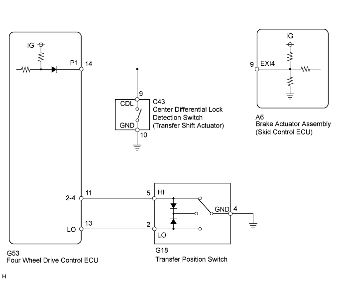
WIRING DIAGRAM
INSPECTION PROCEDURE
Note
When replacing the brake actuator assembly, perform calibration Click here.
PROCEDURE
-
INSPECT CENTER DIFFERENTIAL LOCK SHIFT
-
Check that the center differential can shift from free to lock, and from lock to free.
OK The center differential can shift from free to lock, and from lock to free.
NG 
CHECK TERMINAL VOLTAGE (EXI4) Click here
OK 
-
-
CHECK TEST MODE DTC
-
Switch the vehicle to test mode, perform the center differential lock signal check, and then check that DTC C1282 is cleared Click here.
Result Result Proceed to DTC is not cleared A DTC is cleared B
B 
USE SIMULATION METHOD TO CHECK Click here
A 
REPLACE BRAKE ACTUATOR ASSEMBLY Click here
-
-
CHECK TERMINAL VOLTAGE (EXI4)
-
Set the vehicle in the center differential locked state using the center differential lock switch.
-
Disconnect the A6 skid control ECU connector.
-
Turn the ignition switch to ON.
-
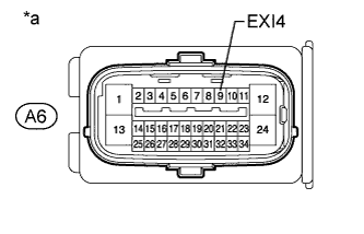
Text in Illustration *a Front view of wire harness connector
(to Skid Control ECU)
Measure the voltage according to the value(s) in the table below.
Standard Voltage Tester Connection Condition Specified Condition A6-9 (EXI4) - Body ground Center differential locked
(Center differential lock switch on)
Below 1.5 V -
Connect the A6 skid control ECU connector.
-
Set the vehicle in the center differential free state using the center differential lock switch.
-
Disconnect the A6 skid control ECU connector.
-
Turn the ignition switch to ON.
-
Measure the voltage according to the value(s) in the table below.
Standard Voltage Tester Connection Condition Specified Condition A6-9 (EXI4) - Body ground Center differential free
(Center differential lock switch off)
11 to 14 V
NG
CHECK HARNESS AND CONNECTOR (SKID CONTROL ECU - FOUR WHEEL DRIVE CONTROL ECU/TRANSFER SHIFT ACTUATOR) Click here
OK
-
-
CHECK TEST MODE DTC
-
Switch the vehicle to test mode, perform the center differential lock signal check, and then check that DTC C1282 is cleared Click here.
Result Result Proceed to DTC is not cleared A DTC is cleared B
B
USE SIMULATION METHOD TO CHECK Click here
A
REPLACE BRAKE ACTUATOR ASSEMBLY Click here
-
-
CHECK HARNESS AND CONNECTOR (SKID CONTROL ECU - FOUR WHEEL DRIVE CONTROL ECU/TRANSFER SHIFT ACTUATOR)
-
Disconnect the A6 skid control ECU connector.
-
Disconnect the G53 four wheel drive control ECU connector.
-
Disconnect the C43 transfer shift actuator connector.
-
Measure the resistance according to the value(s) in the table below.
Standard Resistance Tester Connection Condition Specified Condition A6-9 (EXI4) - G53-14 (P1) Always Below 1 Ω A6-9 (EXI4) - C43-9 (CDL) Always Below 1 Ω A6-9 (EXI4) - Body ground Always 10 kΩ or higher
NG
REPAIR OR REPLACE HARNESS OR CONNECTOR
OK
GO TO TRANSFER SYSTEM (PROBLEM SYMPTOMS TABLE) Click here
-