VEHICLE STABILITY CONTROL SYSTEM (for Vacuum Brake Booster) DTC CHECK / CLEAR

-
DTC CHECK/CLEAR (When Using Intelligent Tester)
-
Check for DTCs.
-
Turn the ignition switch off.
-
Connect the intelligent tester to the DLC3.
-
Turn the ignition switch to ON.
-
Turn the intelligent tester on.
-
Enter the following menus: Chassis / ABS/VSC/TRC / DTC.
-
Check the details of the DTCs Click here.
Tech Tips
Refer to the intelligent tester operator's manual for further details.
-
-
Clear the DTCs.
-
Turn the ignition switch off.
-
Connect the intelligent tester to the DLC3.
-
Turn the ignition switch to ON.
-
Turn the intelligent tester on.
-
Enter the following menus: Chassis / ABS/VSC/TRC / DTC.
-
Clear the DTCs by following the prompts on the intelligent tester.
Tech Tips
Refer to the intelligent tester operator's manual for further details.
-
-
-
DTC CHECK/CLEAR (When Using SST Check Wire)
-
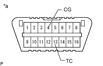
Text in Illustration *a Front view of DLC3 Check for DTCs.
-
Using SST, connect terminals 13 (TC) and 4 (CG) of the DLC3.
- SST
- 09843-18040
-
Turn the ignition switch to ON.
-
Read the DTCs output from the ABS warning light and slip indicator light in the combination meter.
Tech Tips
-
When the system is normal, the ABS warning light and slip indicator light blink at 0.25 second intervals (0.25 seconds on and 0.25 seconds off).
-
When only 1 DTC is output, the light outputs the same code after an interval of 4 seconds. Example: when DTC 21 is output, the light blinks twice, turns off for 1.5 seconds, blinks once, turns off for 4 seconds, and then repeats this output pattern.
-
When 2 or more DTCs are output, the light outputs the codes with an interval of 2.5 seconds between each different code, and the output of all codes repeats after an interval of 4 seconds.
-
If no code is output, inspect the TC and CG terminal circuit and ABS warning and slip indicator light circuits.
Trouble Area See Procedure TC and CG terminal circuit ABS warning light circuit (Remains on) ABS warning light circuit (Does not come on) Slip indicator light circuit (Remains on) Slip indicator light circuit (Does not come on) -
-
Codes are explained in the DTC chart.
ABS DTC ABS Warning Light Display Intelligent Tester Display 11 C0278 12 C0279 13 C0273 14 C0274 21 C0226 22 C0236 23 C0246 24 C0256 25 C1225 31 C1401 C1405 C1409 32 C1402 C1406 C1410 33 C1403 C1407 C1411 34 C1404 C1408 C1412 35 C1413 36 C1414 37 C1337 38 C1415 39 C1416 41 C1241 C1417 43 C1243 44 C1419 C1420 C1442 45 C1245 46 C1421 C1422 C1423 C1424 49 C1425 C1426 51 C1427 C1428 59 C1203 67 C1429 C1430 C1431 68 C1268 91 C1361 94 U0073 95 U0124 97 C1381 A1* U0114
-
*: The light blinks 10 times, turns off for 1.5 seconds, and then blinks once.
VSC DTC Slip Indicator Light Display Intelligent Tester Display 31 C1432 C1433 C1434 32 C1232 34 C1435 C1436 C1443 36 C1210 39 C1336 43* - 51 C1201 53 C1203 62 U0123 63 U0126 65 C1437 U0100 66 C1290 C1439 C1445 98 C1440 C1441
-
*: This DTC is stored when the VSC system detects a malfunction in the ABS.
-
-
Disconnect terminals 13 (TC) and 4 (CG) of the DLC3.
Tech Tips
If 2 or more DTCs are output at the same time, the DTCs are output in ascending order.
-
-
Clear the DTCs.
-
Text in Illustration *a Front view of DLC3 Using SST, connect terminals 13 (TC) and 4 (CG) of the DLC3.
- SST
- 09843-18040
-
Turn the ignition switch to ON.
-
Clear the DTCs stored in the ECU by depressing the brake pedal 8 times or more within 5 seconds.
-
Check that the ABS warning light and slip indicator light blink at 0.25 second intervals (0.25 seconds on and 0.25 seconds off).
-
Remove SST from the terminals of the DLC3.
-
-
-
END OF DTC CHECK/CLEAR
-
Turn the ignition switch to ON.
-
Check that the ABS warning light and slip indicator light go off within approximately 3 seconds after turning the ignition switch to ON.
-