VEHICLE STABILITY CONTROL SYSTEM (for Hydraulic Brake Booster), Diagnostic DTC:C1379

| DTC Code | DTC Name |
|---|---|
| C1379 | Downhill Assist Control Switch Malfunction (Test Mode DTC) |
DESCRIPTION
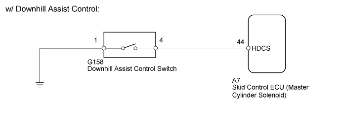
w/ Downhill Assist Control:
DTC C1379 is cleared when the downhill assist control switch sends a downhill assist control operation signal or when test mode ends.
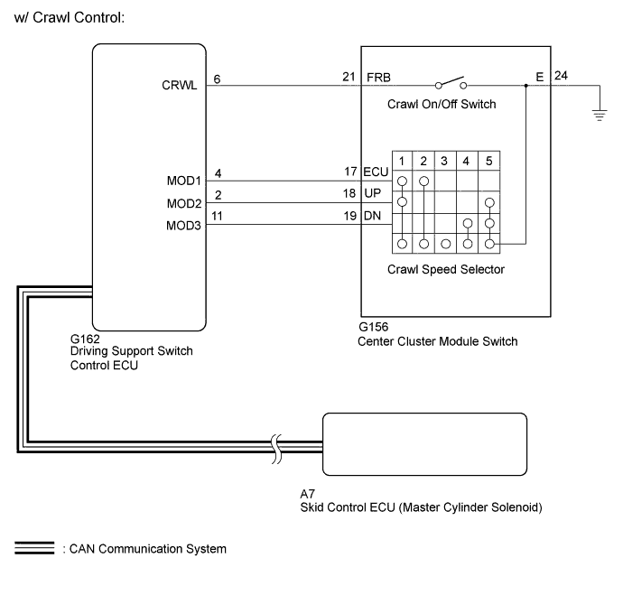
w/ Crawl Control:
DTC C1379 is cleared when the crawl on/off switch (center cluster module switch) and crawl speed selector (center cluster module switch) send a crawl control operation signal or when test mode ends.
| DTC Code | DTC Detection Condition | Trouble Area |
|---|---|---|
| C1379 | Stored only during test mode. |
|
WIRING DIAGRAM
INSPECTION PROCEDURE
Note
When replacing the skid control ECU (master cylinder solenoid), perform calibration Click here.
PROCEDURE
-
CONFIRM VEHICLE SPECIFICATIONS
-
Confirm the vehicle specifications.
Result Result Proceed to w/ Downhill Assist Control A w/ Crawl Control B
B 
CHECK CAN BUS Click here
A 
-
-
READ VALUE USING GTS (DOWNHILL ASSIST CONTROL SW)
-
Turn the ignition switch off.
-
Connect the GTS to the DLC3.
-
Turn the ignition switch to ON.
-
Turn the GTS on.
-
Enter the following menus: Chassis / ABS/VSC/TRC / Data List.
-
Check the Data List for proper functioning of the downhill assist control switch.
ABS/VSC/TRC Tester Display Measurement Item/Range Normal Condition Diagnostic Note Downhill Assist Control SW Downhill assist control switch / ON or OFF ON: Downhill assist control on
OFF: Downhill assist control off
- OK The GTS displays ON or OFF according to downhill assist control switch operation.
NG
OK
-
-
CHECK TEST MODE DTC
-
Perform the downhill assist control switch check in the Test Mode Procedure Click here.
OK Test mode DTC C1379 is cleared. Result Result Proceed to OK A NG (for LHD) B NG (for RHD) C
B 
REPLACE MASTER CYLINDER SOLENOID Click here
C
REPLACE MASTER CYLINDER SOLENOID Click here
A 
USE SIMULATION METHOD TO CHECK Click here
-
-
INSPECT DOWNHILL ASSIST CONTROL SWITCH
-
Remove the downhill assist control switch Click here.
-
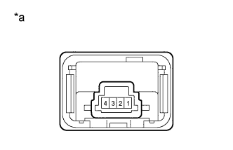
Text in Illustration *a Component without harness connected
(Downhill Assist Control Switch)
Measure the resistance according to the value(s) in the table below.
Standard Resistance Tester Connection Switch Condition Specified Condition 1 - 4 Not pushed in 10 kΩ or higher Pushed in Below 1 Ω
NG
REPLACE DOWNHILL ASSIST CONTROL SWITCH Click here
OK
-
-
CHECK HARNESS AND CONNECTOR (MASTER CYLINDER SOLENOID - DOWNHILL ASSIST CONTROL SWITCH)
-
Disconnect the A7 skid control ECU (master cylinder solenoid) connector.
-
Disconnect the G158 downhill assist control switch connector.
-
Measure the resistance according to the value(s) in the table below.
Standard Resistance Tester Connection Condition Specified Condition A7-44 (HDCS) - G158-4 Always Below 1 Ω A7-44 (HDCS) or G158-4 - Body ground Always 10 kΩ or higher G158-1 - Body ground Always Below 1 Ω Result Result Proceed to NG A OK (for LHD) B OK (for RHD) C
B
REPLACE MASTER CYLINDER SOLENOID Click here
C
REPLACE MASTER CYLINDER SOLENOID Click here
A
REPAIR OR REPLACE HARNESS OR CONNECTOR
-
-
CHECK CAN BUS
-
Check that there are no problems with the CAN communication system (for LHD: Click here, for RHD: Click here.
Result Result Proceed to OK A NG (for LHD) B NG (for RHD) C
B
GO TO CAN COMMUNICATION SYSTEM (HOW TO PROCEED WITH TROUBLESHOOTING) Click here
C
GO TO CAN COMMUNICATION SYSTEM (HOW TO PROCEED WITH TROUBLESHOOTING) Click here
A
-
-
READ VALUE USING GTS (CRAWL CONTROL MAIN SWITCH AND DIAL SWITCH SIGNAL)
-
Turn the ignition switch off.
-
Connect the GTS to the DLC3.
-
Turn the ignition switch to ON.
-
Turn the GTS on.
-
Enter the following menus: Body Electrical / D-SEAT SW / Data List.
-
Check the Data List for proper functioning of the crawl on/off switch (center cluster module switch) and crawl speed selector (center cluster module switch).
D-SEAT SW Tester Display Measurement Item/Range Normal Condition Diagnostic Note Crawl Control Main Switch Crawl on/off switch/ ON or OFF ON: Switch on
OFF: Switch off
- Dial Switch Signal 1 Crawl speed selector/Multi-terrain select road mode selector signal 1/ ON or OFF Switches between ON and OFF according to the ON/OFF Combination Chart below. - Dial Switch Signal 2 Crawl speed selector/Multi-terrain select road mode selector signal 2/ ON or OFF - Dial Switch Signal 3 Crawl speed selector/Multi-terrain select road mode selector signal 3/ ON or OFF -
-
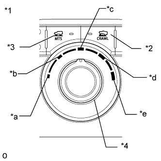
Text in Illustration *1 Center Cluster Module Switch *2 Crawl On/Off Switch *3 Multi-terrain Select Switch *4 Crawl Speed Selector/Multi-terrain Select Road Mode Selector *a Low/MUD & SAND *b Medium-low/LOOSE ROCK *c Medium/MOGUL *d Medium-high/ROCK & DIRT *e High/ROCK Operate the crawl speed selector/multi-terrain select road mode selector and check that "Dial Switch Signal 1", "Dial Switch Signal 2" and "Dial Switch Signal 3" in the Data List display ON and OFF according to the chart shown below.
ON/OFF Combination Chart for "Dial Switch Signal 1", "Dial Switch Signal 2" and "Dial Switch Signal 3" Crawl Speed Selector Position/Multi-terrain Select Road Mode Selector Position Low/MUD & SAND Medium-low/LOOSE ROCK Medium/MOGUL Medium-high/ROCK & DIRT High/ROCK Data List Display Dial Switch Signal 1 ON ON OFF OFF OFF Dial Switch Signal 2 ON OFF OFF OFF ON Dial Switch Signal 3 OFF OFF OFF ON ON OK The GTS display changes according to crawl on/off switch (center cluster module switch) and crawl speed selector (center cluster module switch) operation.
-
NG
CHECK HARNESS AND CONNECTOR (CENTER CLUSTER MODULE SWITCH - DRIVING SUPPORT SWITCH CONTROL ECU) Click here
OK
-
-
CHECK TEST MODE DTC
-
Perform the crawl on/off switch (center cluster module switch) and crawl speed selector (center cluster module switch) check in the Test Mode Procedure Click here.
OK Test mode DTC C1379 is cleared. Result Result Proceed to OK A NG (for LHD) B NG (for RHD) C
B
REPLACE MASTER CYLINDER SOLENOID Click here
C
REPLACE MASTER CYLINDER SOLENOID Click here
A
USE SIMULATION METHOD TO CHECK Click here
-
-
CHECK HARNESS AND CONNECTOR (CENTER CLUSTER MODULE SWITCH - DRIVING SUPPORT SWITCH CONTROL ECU)
-
Disconnect the G156 center cluster module switch connector.
-
Disconnect the G162 driving support switch control ECU connector.
-
Measure the resistance according to the value(s) in the table below.
Standard Resistance Tester Connection Condition Specified Condition G162-6 (CRWL) - G156-21 (FRB) Always Below 1 Ω G162-4 (MOD1) - G156-17 (ECU) Always Below 1 Ω G162-11 (MOD3) - G156-19 (DN) Always Below 1 Ω G162-2 (MOD2) - G156-18 (UP) Always Below 1 Ω G156-24 (E) - Body ground Always Below 1 Ω G162-6 (CRWL) or G156-21 (FRB) - Body ground Always 10 kΩ or higher G162-4 (MOD1) or G156-17 (ECU) - Body ground Always 10 kΩ or higher G162-11 (MOD3) or G156-19 (DN) - Body ground Always 10 kΩ or higher G162-2 (MOD2) or G156-18 (UP) - Body ground Always 10 kΩ or higher
NG
REPAIR OR REPLACE HARNESS OR CONNECTOR
OK
-
-
INSPECT CENTER CLUSTER MODULE SWITCH
-
Remove the center cluster module switch Click here.
-
Inspect the crawl on/off switch (center cluster module switch) and crawl speed selector (center cluster module switch) Click here.
NG
REPLACE CENTER CLUSTER MODULE SWITCH Click here
OK
REPLACE DRIVING SUPPORT SWITCH CONTROL ECU Click here
-