TIRE PRESSURE WARNING SYSTEM Tire Pressure Warning Light Circuit
DESCRIPTION
If the tire pressure warning ECU and receiver detects a disconnected connector or an open circuit between the tire pressure warning ECU and receiver and combination meter assembly, the tire pressure warning light blinks for 1 minute, and then remains on after the ignition switch ON.
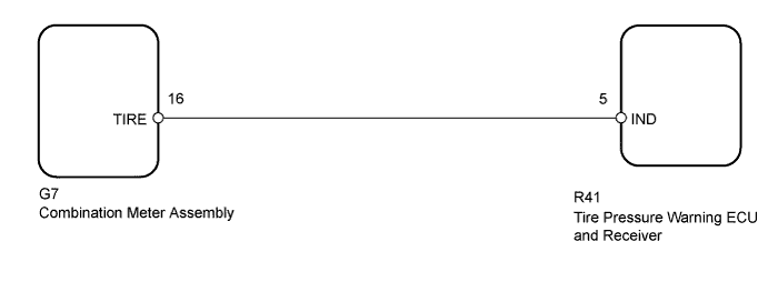
WIRING DIAGRAM
INSPECTION PROCEDURE
Note
-
When replacing the tire pressure warning ECU and receiver, read the transmitter IDs stored in the old ECU using the GTS and write them down before removal.
-
It is necessary to perform initialization Click here after registration Click here of the transmitter IDs into the tire pressure warning ECU and receiver if the ECU has been replaced.
PROCEDURE
-
CHECK HARNESS AND CONNECTOR (COMBINATION METER ASSEMBLY - ECU)
-
Disconnect the tire pressure warning ECU and receiver R41 connector.
-
Disconnect the combination meter assembly G7 connector.
-
Measure the resistance according to the value(s) in the table below.
Standard Resistance Tester Connection Condition Specified Condition R41-5 (IND) - G7-16 (TIRE) Always Below 1 Ω R41-5 (IND) or G7-16 (TIRE) - Body ground Always 10 kΩ or higher
NG 
REPAIR OR REPLACE HARNESS OR CONNECTOR
OK 
-
-
CHECK OPERATION OF TIRE PRESSURE WARNING LIGHT (ACTIVE TEST)
-
Turn the ignition switch off.
-
Connect the GTS to the DLC3.
-
Turn the ignition switch ON.
-
Turn the GTS on.
-
Enter the following menus: Body Electrical / Combination Meter / Active Test.
-
Check the condition of the tire pressure warning light by using the GTS.
Combination Meter Tester Display Test Part Control Range Diagnostic Note Indicat. Tire Pressure Warning System Tire pressure warning light OFF or ON Confirm that the vehicle is stopped with the engine idling. OK The tire pressure warning light turns on or off in accordance with the GTS operation.
NG
GO TO METER / GAUGE SYSTEM Click here
OK 
REPLACE TIRE PRESSURE WARNING ECU AND RECEIVER Click here
-