-
Use the same procedure for the RH and LH sides.
-
The procedure listed below is for the LH side.
-
A bolt without a torque specification is shown in the standard bolt chart (Click here).
- Click here
TEMPORARILY INSTALL FRONT NO. 1 SUSPENSION LOWER ARM SUB-ASSEMBLY LH
-
Temporarily install the lower suspension arm, camber adjust cam, No. 2 camber adjust cam, No. 2 toe adjust plate and toe adjust cam with the bolt and nut.
-
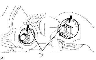
Align the matchmarks on the No. 2 camber adjust cam and toe adjust cam sub-assembly with the matchmarks on the vehicle body. Tighten the bolt and nut.
Table 1. Text in Illustration *a Matchmark -
Install the front lower ball joint attachment LH with a new nut and cotter pin.
140 N*m 1428 kgf*cm 103 ft.*lbf -
Connect the front lower ball joint attachment LH to the front axle with the 2 bolts.
160 N*m 1632 kgf*cm 118 ft.*lbf
-
- Click here
TEMPORARILY INSTALL FRONT SHOCK ABSORBER WITH COIL SPRING
-
Temporarily install the front shock absorber with coil spring and washer with the bolt and nut.
-
- Click here
INSTALL FRONT STABILIZER BAR (w/ KDSS)
-
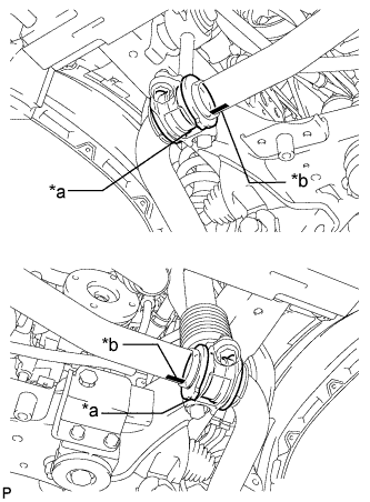
Install the 2 front stabilizer lower bracket bushes to the front stabilizer bar.
Tip:Align the protrusions on the bushes with the identification marks on the front stabilizer bar with the protrusions facing inward.
Table 2. Text in Illustration *a Protrusion *b Mark Position -
With the identification marks of the front stabilizer bar facing downwards, support the front stabilizer bar with a jack.
Note:Place a wooden block between the jack and front stabilizer bar to prevent damage.
Tip:Place the jack under the center of the vehicle.
-
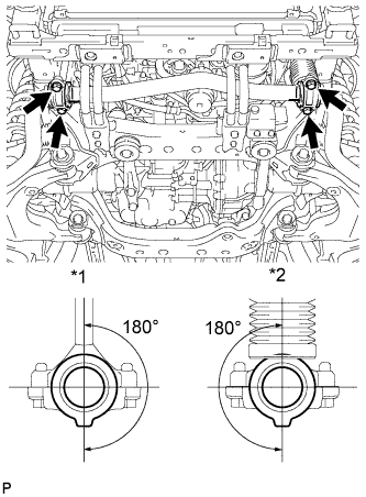
Install the front stabilizer bar and 2 front stabilizer lower brackets with the 4 bolts.
40 N*m 408 kgf*cm 30 ft.*lbf Tip:Make sure that the protrusions on the front stabilizer lower bracket bushes are positioned within 180° of the stabilizer cylinder and stabilizer link.
Table 3. Text in Illustration *1 Stabilizer Link *2 Stabilizer Cylinder
-
- Click here
INSTALL FRONT STABILIZER END BRACKET (w/ KDSS)
-
Install the 2 front stabilizer brackets and 2 front stabilizer link bushes with the 4 bolts.
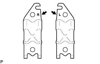
75 N*m 765 kgf*cm 55 ft.*lbf Tip:There are stamps on the front stabilizer brackets to distinguish between the right and left brackets.
-
- Click here
INSTALL FRONT SUSPENSION MEMBER BRACE SUB-ASSEMBLY (w/ KDSS)
-
Install the 2 member braces with the 6 bolts.
30 N*m 306 kgf*cm 22 ft.*lbf
-
- Click here
INSTALL NO. 1 ENGINE UNDER COVER SUB-ASSEMBLY (w/ KDSS)
-
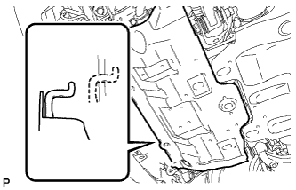
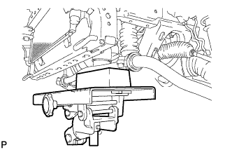
Hook the engine under cover to the vehicle body as shown in the illustration.
-
Install the 4 bolts.
29 N*m 296 kgf*cm 21 ft.*lbf
-
- Click here
INSTALL LOWER FRONT BUMPER COVER (w/ KDSS)
-
Install the front bumper cover lower with the 5 bolts and clip.
8.0 N*m 82 kgf*cm 71 in.*lbf
-
- Click here
INSTALL FRONT WHEEL
112 N*m 1142 kgf*cm 83 ft.*lbf - Click here
STABILIZE SUSPENSION
-
Lower the vehicle.
-
Bounce the vehicle up and down several times to stabilize the suspension.
-
- Click here
TIGHTEN FRONT NO. 1 SUSPENSION LOWER ARM SUB-ASSEMBLY LH
-
Tighten the bolt and nut.
175 N*m 1785 kgf*cm 129 ft.*lbf
-
- Click here
TIGHTEN FRONT SHOCK ABSORBER WITH COIL SPRING
-
Tighten the nut.
95 N*m 969 kgf*cm 70 ft.*lbf
-
- Click here
INSPECT AND ADJUST FRONT WHEEL ALIGNMENT
-
Inspect and adjust the front wheel alignment (Click here).
-