FRONT SHOCK ABSORBER INSTALLATION

Tech Tips
-
Use the same procedure for the RH and LH sides.
-
The procedure listed below is for the LH side.
-
A bolt without a torque specification is shown in the standard bolt chart Click here.
-
TEMPORARILY INSTALL FRONT SHOCK ABSORBER WITH COIL SPRING (w/ Air Suspension)
-
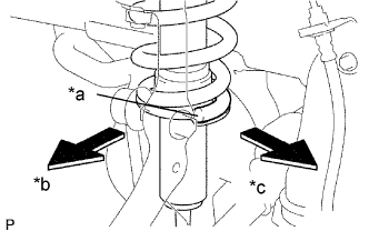
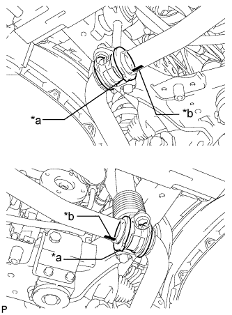
Text in Illustration *a Lower End *b Outer Side *c Rear Side Install the coil spring to the vehicle body with the lower end of the coil spring facing the rear side of the vehicle.
-
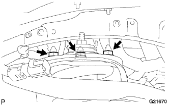
Install the 3 nuts to the top of the front shock absorber with coil spring.
- Torque:
- 64 N*m { 653 kgf*cm, 47 ft.*lbf }
-
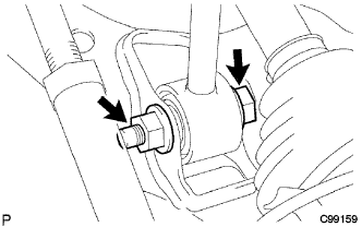
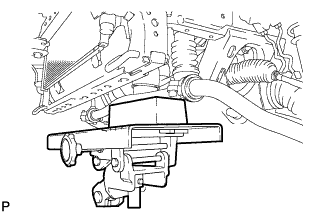
Temporarily install the bolt, washer and nut as shown in the illustration.
-
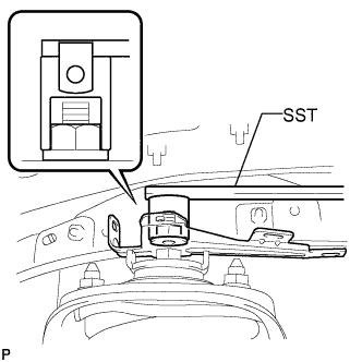
Using SST, install the bracket with the nut.
- SST
- 09961-00950
- Torque:
- 15 N*m { 153 kgf*cm, 11 ft.*lbf }
-
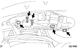
Using a 4 mm hexagon wrench, install the absorber control actuator with the 2 bolts.
- Torque:
- 7.8 N*m { 80 kgf*cm, 69 in.*lbf }
-
Attach the 3 clamps and connect the connector.
-
-
TEMPORARILY INSTALL FRONT SHOCK ABSORBER WITH COIL SPRING (w/o Air Suspension)
-
Text in Illustration *a Lower End *b Outer Side *c Rear Side Install the coil spring to the vehicle body with the lower end of the coil spring facing the rear side of the vehicle.
-
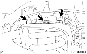
Install the 3 nuts to the upper side of the front shock absorber with coil spring.
- Torque:
- 64 N*m { 653 kgf*cm, 47 ft.*lbf }
-
Temporarily install the bolt, washer and nut as shown in the illustration.
-
-
INSTALL FRONT STABILIZER BAR (w/ KDSS)
-
Text in Illustration *a Protrusion *b Mark Position Install the 2 front stabilizer lower bracket bushes to the front stabilizer bar.
Tech Tips
Align the protrusions on the bushes with the identification marks on the front stabilizer bar with the protrusions facing inward.
-
With the identification marks of the front stabilizer bar facing downwards, support the front stabilizer bar with a jack.
Note
Place a wooden block between the jack and front stabilizer bar to prevent damage.
Tech Tips
Place the jack under the center of the vehicle.
-
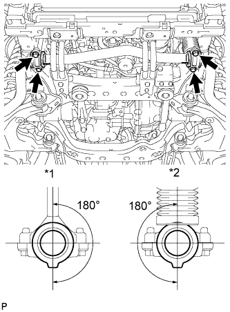
Text in Illustration *1 Stabilizer Link *2 Stabilizer Cylinder Install the front stabilizer bar and 2 front stabilizer lower brackets with the 4 bolts.
- Torque:
- 40 N*m { 408 kgf*cm, 30 ft.*lbf }
Tech Tips
Make sure that the protrusions on the front stabilizer lower bracket bushes are positioned within 180° of the stabilizer cylinder and stabilizer link.
-
-
INSTALL FRONT STABILIZER END BRACKET (w/ KDSS)
-
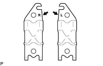
Install the 2 front stabilizer brackets and 2 front stabilizer link bushes with the 4 bolts.
- Torque:
- 75 N*m { 765 kgf*cm, 55 ft.*lbf }
Tech Tips
There are stamps on the front stabilizer brackets to distinguish between the right and left brackets.
-
-
INSTALL FRONT STABILIZER BAR (w/o KDSS)
-
INSTALL FRONT NO. 1 STABILIZER BRACKET LH (w/o KDSS)
-
Install the front No. 1 stabilizer bracket LH with the 2 bolts.
- Torque:
- 49 N*m { 500 kgf*cm, 36 ft.*lbf }
-
-
INSTALL FRONT NO. 1 STABILIZER BRACKET RH (w/o KDSS)
Tech Tips
Use the same procedure described for the LH side.
-
CONNECT FRONT STABILIZER LINK ASSEMBLY LH (w/o KDSS)
-
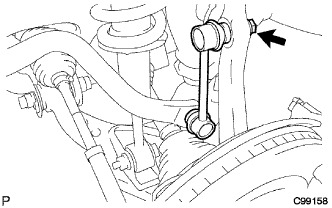
Connect the stabilizer link to the steering knuckle with the nut.
- Torque:
- 70 N*m { 710 kgf*cm, 52 ft.*lbf }
Tech Tips
If the ball joint turns together with the nut, use a 6 mm hexagon wrench to hold the stud.
-
-
CONNECT FRONT STABILIZER LINK ASSEMBLY RH (w/o KDSS)
Tech Tips
Use the same procedure described for the LH side.
-
INSTALL FRONT SUSPENSION MEMBER BRACE SUB-ASSEMBLY
-
Install the 2 member braces with the 6 bolts.
- Torque:
- 30 N*m { 306 kgf*cm, 22 ft.*lbf }
-
-
INSTALL NO. 1 ENGINE UNDER COVER SUB-ASSEMBLY
-
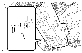
Hook the engine under cover to the vehicle body as shown in the illustration.
-
Install the 4 bolts.
- Torque:
- 29 N*m { 296 kgf*cm, 21 ft.*lbf }
-
-
INSTALL LOWER FRONT BUMPER COVER
-
Install the front bumper cover lower with the 5 bolts and clip.
- Torque:
- 8.0 N*m { 82 kgf*cm, 71 in.*lbf }
-
-
INSTALL FRONT WHEEL
- Torque:
- 112 N*m { 1142 kgf*cm, 83 ft.*lbf }
-
STABILIZE SUSPENSION
-
Lower the vehicle.
-
Bounce the vehicle up and down several times to stabilize the suspension.
-
-
TIGHTEN FRONT SHOCK ABSORBER WITH COIL SPRING
-
Tighten the nut.
- Torque:
- 95 N*m { 969 kgf*cm, 70 ft.*lbf }
-
-
INSPECT AND ADJUST FRONT WHEEL ALIGNMENT
-
Inspect and adjust the front wheel alignment Click here.
-