-
Click here
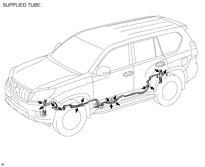
INSTALL FRONT NO. 1 STABILIZER CONTROL TUBE ASSEMBLY
-
Using a union nut wrench, disconnect the 2 flare nuts of a new front No. 1 stabilizer control tube assembly.
-
Remove the bolt and clamp from the front No. 1 stabilizer control tube assembly.
-
Disassemble the front No. 1 stabilizer control tube assembly.
-
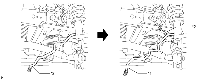
Pull the front No. 1 stabilizer control tube assembly (upper part) and front No. 1 stabilizer control tube assembly (lower part) through the vehicle.
Table 1. Text in Illustration *1 Front No. 1 Stabilizer Control Tube Assembly (Upper Part) *2 Front No. 1 Stabilizer Control Tube Assembly (Lower Part) -
Temporarily install the 2 flare nuts on the front No. 1 stabilizer control tube assembly (front stabilizer with tube cylinder assembly side).
-
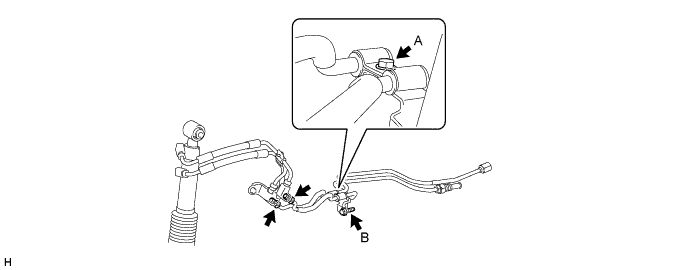
Install the clamp to the front No. 1 stabilizer control tube assembly with the bolt (labeled A).
-
Connect the clamp to the body with the bolt (labeled B).
29 N*m 296 kgf*cm 21 ft.*lbf -
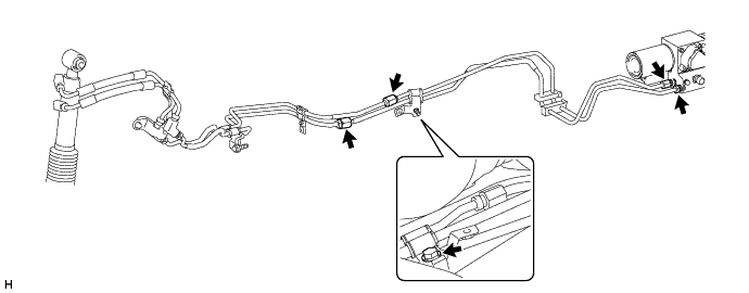
Temporarily install the 4 flare nuts on the disconnected end of the front No. 1 stabilizer control tube assembly (stabilizer control with accumulator housing side).
-
Connect the clamp to the body with the bolt.
-
Tighten the 6 flare nuts on the front No. 1 stabilizer control tube assembly.
44 N*m 450 kgf*cm 33 ft.*lbf Note:Use the formula to calculate special torque values for situations where a union nut wrench is combined with a torque wrench (Click here).
-
- Click here
INSTALL FRONT STABILIZER TUBE PROTECTOR
-
Install the front stabilizer tube protector with the 2 bolts.
29 N*m 296 kgf*cm 21 ft.*lbf
-
-
Click here
INSTALL REAR NO. 1 STABILIZER CONTROL TUBE ASSEMBLY
-
Disconnect the 2 flare nuts of a new rear No. 1 stabilizer control tube assembly.
-
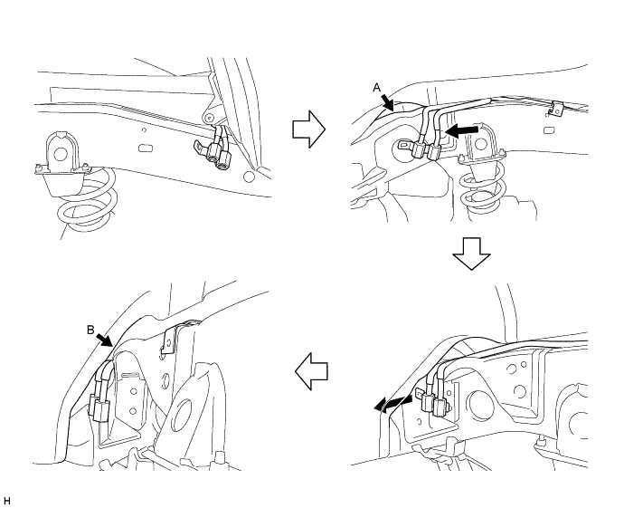
Move the rear No. 1 stabilizer control tube assembly (rear stabilizer control cylinder side) towards the outside of the frame.
-
Using a plastic-faced hammer, lightly tap the rear No. 1 stabilizer control tube assembly (rear stabilizer control cylinder side) and slide it to the left.
Note:
-
Make sure that the rear No. 1 stabilizer control tube assembly is not deformed, as the gaps shown by arrows A and B in the illustration are small.
-
Slide the rear No. 1 stabilizer control tube assembly to the left so that the flare nut part is between the frame and wheel house.
-
If the flare nut part protrudes on the wheel house side, move the part back to the rear of the vehicle and slide it once again to install it.
-
-
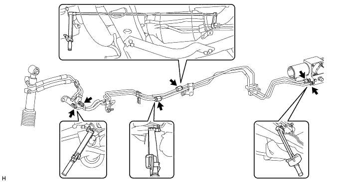
Temporarily install the 4 flare nuts on the disconnected end of the rear No. 1 stabilizer control tube assembly (stabilizer control with accumulator housing side).
-
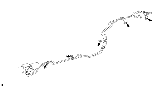
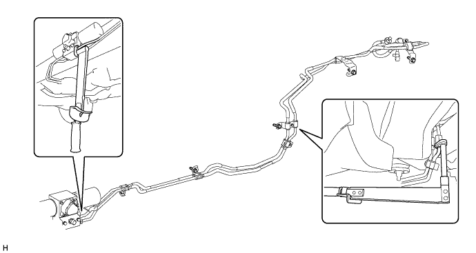
Install the rear No. 1 stabilizer control tube assembly with the 5 bolts.
29 N*m 296 kgf*cm 21 ft.*lbf -
Tighten the 4 flare nuts on the rear No. 1 stabilizer control tube assembly.
44 N*m 450 kgf*cm 33 ft.*lbf Note:Use the formula to calculate special torque values for situations where a union nut wrench is combined with a torque wrench (Click here).
-
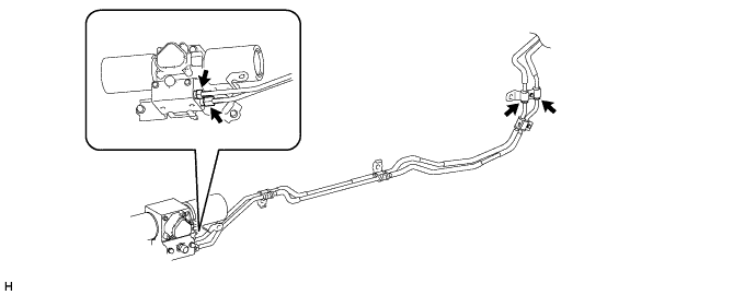
Install the rear stabilizer control tubes to the rear stabilizer control cylinder with the 2 union bolts and 2 new pressure port gaskets.
48 N*m 484 kgf*cm 35 ft.*lbf Note:Insert the stoppers of the rear stabilizer control tubes into the rear stabilizer control cylinder.
-
- Click here
INSTALL REAR SHOCK ABSORBER ASSEMBLY LH
- Click here
INSTALL FUEL PUMP CONTROL ECU ASSEMBLY
-
Install the fuel pump ECU with the 2 bolts.
31 N*m 316 kgf*cm 23 ft.*lbf Note:Do not use the fuel pump ECU if it has been subjected to physical shocks, such as being dropped, etc.
-
Connect the 2 connectors.
-
- Click here
BLEED AIR FROM SUSPENSION FLUID
CAUTION:
-
Be sure to check the pipe connections and whether or not any hydraulic circuit parts are damaged before performing work as the hydraulic circuits become highly pressurized during air bleeding.
-
The pipes become highly pressurized when bleeding air. If a fluid leak is discovered, immediately release the pressure and repair the fluid leak as there is danger involved.
Tip:When bleeding air, approximately 6 liters of new fluid is needed.
-
Remove the stabilizer control valve protector (Click here).
-
Check the pipe connections and whether or not any hydraulic circuit parts are damaged.
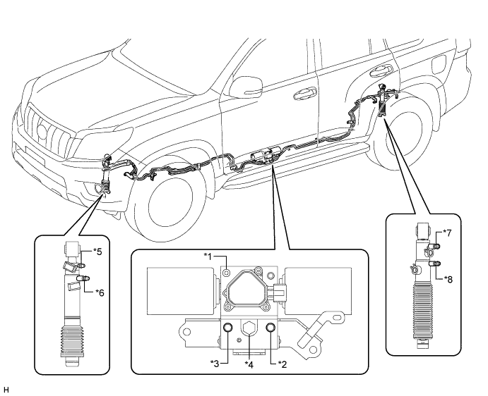
Table 2. Text in Illustration *1 Stabilizer Control with Accumulator Housing Bleeder Plug *2 Upper Chamber Stabilizer Control with Accumulator Housing Shutter Valve *3 Lower Chamber Stabilizer Control with Accumulator Housing Shutter Valve *4 Stabilizer Control Accumulator Housing Inlet Port *5 Front Stabilizer Control Cylinder Upper Chamber Bleeder Plug *6 Front Stabilizer Control Cylinder Lower Chamber Bleeder Plug *7 Rear Stabilizer Control Cylinder Upper Chamber Bleeder Plug *8 Rear Stabilizer Control Cylinder Lower Chamber Bleeder Plug -
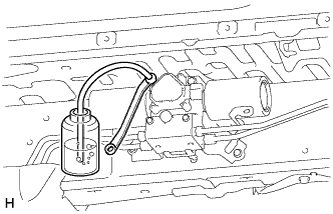
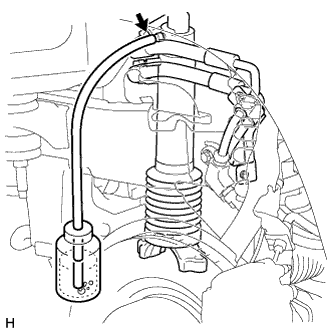
Add new fluid to SST (high pressure oil pump) and bleed air from SST hoses.
09760-60020 Fluid Suspension fluid AHC Note:If air is not bled from the hoses, the air will mix into the hydraulic circuit.
-
Remove the service valve cap. Then put fluid into SST (high pressure oil pump) and connect SST to the suspension fluid inlet port.
-
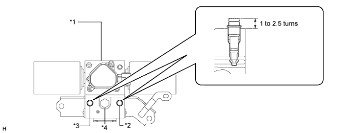
Loosen the shutter valves of the stabilizer control with accumulator housing.
Table 3. Text in Illustration *1 Stabilizer Control with Accumulator Housing Assembly *2 Upper Chamber Stabilizer Control with Accumulator Housing Shutter Valve *3 Lower Chamber Stabilizer Control with Accumulator Housing Shutter Valve *4 Stabilizer Control Accumulator Housing Inlet Port Note:
-
When loosening a shutter valve, loosen it 1 to 2.5 turns, but do not loosen it any more than that.
-
As air may enter the system or fluid may spray out, do not remove the shutter valves.
-
-
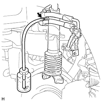
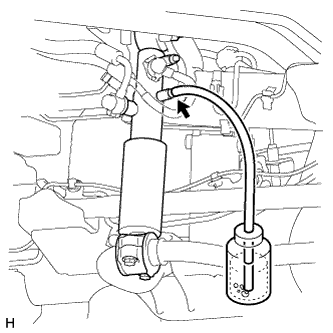
Using SST (high pressure oil pump), add fluid.
CAUTION:If a fluid leak is discovered, immediately release the pressure and repair the fluid leak as there is danger involved due to the high pressure.
Note:Do not allow the pressure to reach 8 MPa (81.6 kgf/cm2, 1160 psi) or higher as the accumulator may be damaged.
-
Pump SST (high pressure oil pump) to add fluid until the pressure reaches 5 MPa (51.0 kgf/cm2, 725 psi).*1
-
Check for fluid leaks from the pipe connections and hydraulic circuit parts.
-
Add fluid to the stabilizer control with accumulator housing.*2
-
Loosen the bleeder plug of the stabilizer control with accumulator housing.
-
Pump SST (high pressure oil pump) and maintain a pressure of 5 MPa (51.0 kgf/cm2, 725 psi) until air stops coming out.
-
Tighten the bleeder plug of the stabilizer control with accumulator housing.
8.3 N*m 85 kgf*cm 73 in.*lbf -
-
Add fluid to the lower chamber of the front stabilizer control cylinder.*3
-
Pump SST (high pressure oil pump) to add fluid until the pressure reaches 5 MPa (51.0 kgf/cm2, 725 psi).
-
Loosen the lower chamber bleeder plug of the front stabilizer control cylinder.
-
Pump SST (high pressure oil pump) and maintain a pressure of 5 MPa (51.0 kgf/cm2, 725 psi) until air stops coming out.
-
Tighten the lower chamber bleeder plug of the front stabilizer control cylinder.
7.9 N*m 81 kgf*cm 70 in.*lbf -
-
Add fluid to the upper chamber of the front stabilizer control cylinder.*4
-
Pump SST (high pressure oil pump) to add fluid until the pressure reaches 5 MPa (51.0 kgf/cm2, 725 psi).
-
Loosen the upper chamber bleeder plug of the front stabilizer control cylinder.
-
Pump SST (high pressure oil pump) and maintain a pressure of 5 MPa (51.0 kgf/cm2, 725 psi) until air stops coming out.
-
Tighten the upper chamber bleeder plug of the front stabilizer control cylinder.
7.9 N*m 81 kgf*cm 70 in.*lbf -
-
Add fluid to the lower chamber of the rear stabilizer control cylinder.*5
-
Pump SST (high pressure oil pump) to add fluid until the pressure reaches 5 MPa (51.0 kgf/cm2, 725 psi).
-
Loosen the lower chamber bleeder plug of the rear stabilizer control cylinder.
-
Pump SST (high pressure oil pump) and maintain a pressure of 5 MPa (51.0 kgf/cm2, 725 psi) until air stops coming out.
-
Tighten the lower chamber bleeder plug of the rear stabilizer control cylinder.
7.9 N*m 81 kgf*cm 70 in.*lbf -
-
Add fluid to the upper chamber of the rear stabilizer control cylinder.*6
-
Pump SST (high pressure oil pump) to add fluid until the pressure reaches 5 MPa (51.0 kgf/cm2, 725 psi).
-
Loosen the upper chamber bleeder plug of the rear stabilizer control cylinder.
-
Pump SST (high pressure oil pump) and maintain a pressure of 5 MPa (51.0 kgf/cm2, 725 psi) until air stops coming out.
-
Tighten the upper chamber bleeder plug of the rear stabilizer control cylinder.
7.9 N*m 81 kgf*cm 70 in.*lbf -
-
Repeat procedures *1 to *6 until the air in the fluid is gone.
-
-
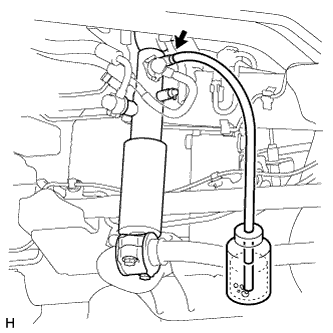
Using SST (high pressure oil pump), bleed the air.
Note:
-
Be sure to apply 7 MPa (71.4 kgf/cm2, 1015 psi) of pressure to all parts. If the pressure is low, the air may not be released.
-
Do not allow the pressure to reach 8 MPa (81.6 kgf/cm2, 1160 psi) or higher as the accumulator may be damaged.
-
Bleed air from the stabilizer control with accumulator housing.
-
Pump SST (high pressure oil pump) to apply 7 MPa (71.4 kgf/cm2, 1015 psi) of pressure.
-
Loosen the bleeder plug of the stabilizer control with accumulator housing to bleed the air.
-
Tighten the bleeder plug so pressure can be applied. Repeat these steps until the air in the fluid is gone.
-
Tighten the bleeder plug of the stabilizer control with accumulator housing.
8.3 N*m 85 kgf*cm 73 in.*lbf -
-
Bleed air from the upper chamber of the front stabilizer control cylinder.
-
Pump SST (high pressure oil pump) to apply 7 MPa (71.4 kgf/cm2, 1015 psi) of pressure.
-
Loosen the upper chamber bleeder plug of the front stabilizer control cylinder to bleed the air.
-
Tighten the bleeder plug so pressure can be applied. Repeat these steps until the air in the fluid is gone.
-
Tighten the upper chamber bleeder plug of the front stabilizer control cylinder.
7.9 N*m 81 kgf*cm 70 in.*lbf -
-
Bleed air from the upper chamber of the rear stabilizer control cylinder.
-
Pump SST (high pressure oil pump) to apply 7 MPa (71.4 kgf/cm2, 1015 psi) of pressure.
-
Loosen the upper chamber bleeder plug of the rear stabilizer control cylinder to bleed the air.
-
Tighten the bleeder plug so pressure can be applied. Repeat these steps until the air in the fluid is gone.
-
Tighten the upper chamber bleeder plug of the rear stabilizer control cylinder.
7.9 N*m 81 kgf*cm 70 in.*lbf -
-
-
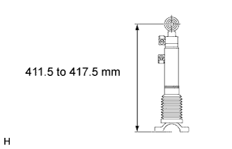
Disconnect the front stabilizer control arm and front stabilizer link, and set the front stabilizer control cylinder to the maximum length.
Maximum length 411.5 to 417.5 mm (16.2 to 16.4 in.) Note:Set the front stabilizer control cylinder to the maximum length to completely bleed the air.
Tip:Refer to the following procedures to disconnect the front stabilizer control arm and front stabilizer link (Click here).
-
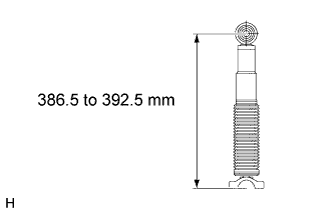
Disconnect the rear stabilizer bar and rear stabilizer link, and set the rear stabilizer control cylinder to the maximum length.
Maximum length 386.5 to 392.5 (15.2 to 15.4 in.) Note:Set the rear stabilizer control cylinder to the maximum length to completely bleed the air.
Tip:Refer to the following procedures to disconnect the rear stabilizer bar and rear stabilizer link (Click here).
-
Bleed air from the lower chamber of the front stabilizer control cylinder.
-
Pump SST (high pressure oil pump) to apply 7 MPa (71.4 kgf/cm2, 1015 psi) of pressure.
-
Loosen the lower chamber bleeder plug of the front stabilizer control cylinder to bleed the air.
-
Tighten the bleeder plug so pressure can be applied. Repeat these steps until the air in the fluid is gone.
-
Tighten the lower chamber bleeder plug of the front stabilizer control cylinder.
7.9 N*m 81 kgf*cm 70 in.*lbf
-
-
Bleed air from the lower chamber of the rear stabilizer control cylinder.
-
Pump SST (high pressure oil pump) to apply 7 MPa (71.4 kgf/cm2, 1015 psi) of pressure.
-
Loosen the lower chamber bleeder plug of the rear stabilizer control cylinder to bleed the air.
-
Tighten the bleeder plug so pressure can be applied. Repeat these steps until the air in the fluid is gone.
-
Tighten the lower chamber bleeder plug of the rear stabilizer control cylinder.
7.9 N*m 81 kgf*cm 70 in.*lbf
-
-
Connect the front stabilizer control arm to the front stabilizer link and the rear stabilizer bar to the rear stabilizer link.
Tip:
-
For the front side, refer to the following procedures (Click here).
-
For the rear side, refer to the following procedures (Click here).
-
-
With all wheels on the ground, apply the specified amount of pressure using SST. Maintain this pressure for 2 to 3 minutes to stabilize the pressure.
Note:
-
Refer to the Temperature Management Chart when Filling Fluid as the specified pressure changes according to the fluid temperature.
-
Perform the inspection with the vehicle load completely on the suspension.
Tip:
-
Perform this step with the fuel tank full.
-
If there are any parts installed to the vehicle which place any unbalanced load on the left or right side of the vehicle, remove them.
Standard Fluid Pressure Condition Specified Condition Fluid temperature is 20°C (68°F) 2.6 to 3 MPa (26.6 to 30.5 kgf/cm2, 377 to 435 psi)
-
-
Measure vehicle height (Click here).
-
Tighten the shutter valves of the stabilizer control with accumulator housing.
9.0 N*m 92 kgf*cm 80 in.*lbf -
Remove SST (high pressure oil pump) from the suspension fluid inlet port.
Note:Make sure that no pressure is applied to SST (high pressure oil pump).
-
Install the service valve caps to the suspension fluid inlet port.
0.6 N*m 6.0 kgf*cm 5.0 in.*lbf -
Inspect for suspension fluid leaks (Click here).
-
Install the stabilizer control valve protector (Click here).
-
-
Click here
APPLY PRESSURE ACCORDING TO TEMPERATURE MANAGEMENT CHART WHEN FILLING FLUID
Table 4. Text in Illustration *1 2.42 MPa (24.7 kgf/cm2, 351 psi)
*2 2.50 MPa (25.5 kgf/cm2, 363 psi)
*3 2.59 MPa (26.4 kgf/cm2, 376 psi)
*4 2.67 MPa (27.2 kgf/cm2, 387 psi)
*5 2.76 MPa (28.1 kgf/cm2, 400 psi)
*6 2.85 MPa (29.1 kgf/cm2, 413 psi)
*7 2.95 MPa (30.1 kgf/cm2, 428 psi)
*8 3.05 MPa (31.1 kgf/cm2, 442 psi)
*9 3.27 MPa (33.3 kgf/cm2, 474 psi)
*10 3.27 MPa (33.3 kgf/cm2, 474 psi)
*11 3.38 MPa (34.5 kgf/cm2, 490 psi)
*12 2.39 MPa (24.4 kgf/cm2, 347 psi)
*13 2.46 MPa (25.1 kgf/cm2, 357 psi)
*14 2.53 MPa (25.8 kgf/cm2, 367 psi)
*15 2.60 MPa (26.5 kgf/cm2, 377 psi)
*16 2.67 MPa (27.2 kgf/cm2, 387 psi)
*17 2.75 MPa (28.0 kgf/cm2, 399 psi)
*18 2.82 MPa (28.8 kgf/cm2, 409 psi)
*19 2.90 MPa (29.6 kgf/cm2, 421 psi)
*20 2.98 MPa (30.4 kgf/cm2, 432 psi)
*21 3.06 MPa (31.2 kgf/cm2, 444 psi)
*22 3.14 MPa (32.0 kgf/cm2, 455 psi)
- Click here
INSPECT FOR SUSPENSION FLUID LEAK
CAUTION:Fluid is pumped into the system at a high pressure of approximately 3 MPa (30.6 kgf/cm2, 435 psi). If a fluid leak is discovered, immediately release the pressure and repair the fluid leak.
-
Perform a driving test.
-
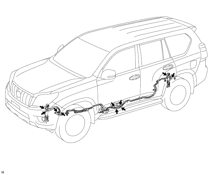
Check for fluid leakage from the parts and connections shown in the illustration.
-
- Click here
INSTALL FRONT WHEEL
112 N*m 1142 kgf*cm 83 ft.*lbf - Click here
INSTALL REAR WHEEL
112 N*m 1142 kgf*cm 83 ft.*lbf - Click here
INSTALL SPARE TIRE
- Click here
MEASURE VEHICLE HEIGHT
Note:
-
Perform the inspection on a level surface.
-
Make sure that the wheels are on the ground and facing straight ahead.
-
Perform the inspection with the vehicle load completely on the suspension.
Tip:
-
Perform this step with the fuel tank full.
-
If there are any parts installed to the vehicle which place any unbalanced load on the left or right side of the vehicle, remove them.
-
Set the tire pressure to the specified value(s) (Click here).
-
Bounce the vehicle to stabilize the suspension.
-
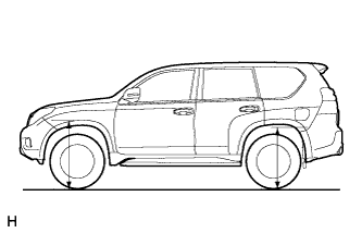
Measure the distance from the ground to the top of the bumper and calculate the difference in the vehicle height between the left and right sides. Perform this procedure for both the front and rear wheels.
Height difference of left and right sides 20 mm (0.787 in.) or less Tip:When the difference in vehicle height between the left and right sides is outside of the specification, perform air bleeding (Click here).
-
- Click here
INSTALL TRANSMISSION UNDER COVER
-
Install the transmission under cover with the 2 bolts.
29 N*m 296 kgf*cm 21 ft.*lbf
-
- Click here
INSTALL NO. 1 ENGINE UNDER COVER SUB-ASSEMBLY
-
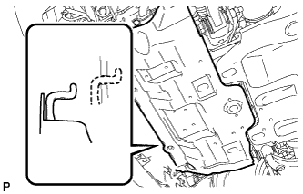
Hook the engine under cover to the vehicle body as shown in the illustration.
-
Install the 4 bolts.
29 N*m 296 kgf*cm 21 ft.*lbf
-
- Click here
INSTALL FRONT BUMPER COVER LOWER
-
Install the front bumper cover lower with the 5 bolts and clip.
8.0 N*m 82 kgf*cm 71 in.*lbf
-
- Click here
INSTALL STABILIZER CONTROL VALVE PROTECTOR
-
Install the stabilizer control valve protector with the 2 bolts.
29 N*m 296 kgf*cm 21 ft.*lbf
-
- Click here
INSTALL SIDE STEP ASSEMBLY LH
-
Install the side step with the 6 bolts.
18 N*m 184 kgf*cm 13 ft.*lbf -
w/ Illumination:
Connect the 2 connectors.
-
- Click here
CONNECT CABLE TO NEGATIVE BATTERY TERMINAL
Note:When disconnecting the cable, some systems need to be initialized after the cable is reconnected (Click here).