STABILIZER CONTROL TUBE (w/ KDSS) REMOVAL

-
DISCONNECT CABLE FROM NEGATIVE BATTERY TERMINAL
CAUTION:
Wait at least 90 seconds after disconnecting the cable from the negative (-) battery terminal to disable the SRS system.
Note
-
After turning the ignition switch off, waiting time may be required before disconnecting the cable from the battery terminal. Therefore, make sure to read the disconnecting the cable from the battery terminal notice before proceeding with work Click here.
-
When disconnecting the cable, some systems need to be initialized after the cable is reconnected Click here.
-
-
REMOVE FRONT WHEEL LH
-
REMOVE REAR WHEEL LH
-
REMOVE SPARE TIRE
-
REMOVE SIDE STEP ASSEMBLY LH
-
w/ Illumination:
Disconnect the 2 connectors.
-
Remove the 6 bolts and side step.
-
-
REMOVE FRONT BUMPER COVER LOWER
-
Remove the clip, 5 bolts and front bumper cover lower.
-
-
REMOVE NO. 1 ENGINE UNDER COVER SUB-ASSEMBLY
-
Remove the 4 bolts.
-
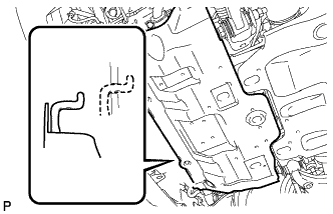
Unhook the engine under cover from the vehicle body as shown in the illustration.
-
-
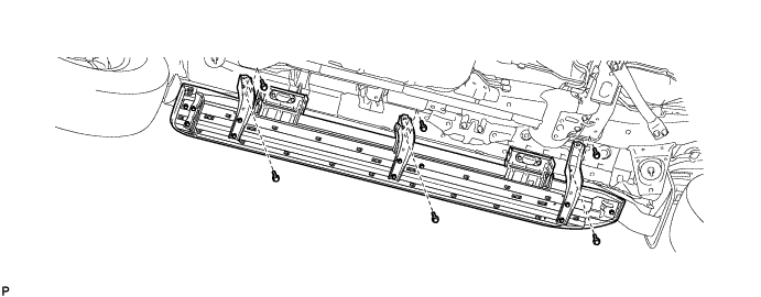
REMOVE TRANSMISSION UNDER COVER
-
Remove the 2 bolts and transmission under cover.
-
-
REMOVE STABILIZER CONTROL VALVE PROTECTOR
-
Remove the 2 bolts and stabilizer control valve protector.
-
-
DRAIN SUSPENSION FLUID
-
Loosen the bleeder plug on the stabilizer control with accumulator housing assembly and drain suspension fluid.
Tech Tips
-
Drain suspension fluid when performing operations related to the hydraulic circuits.
-
Draining suspension fluid decreases suspension fluid pressure.
-
-
Tighten the bleeder plug.
- Torque:
- 8.3 N*m { 85 kgf*cm, 73 in.*lbf }
-
-
REMOVE FRONT STABILIZER TUBE PROTECTOR
-
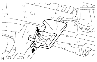
Remove the 2 bolts and front stabilizer tube protector.
-
-
REMOVE FRONT STABILIZER CONTROL TUBE INSULATOR
-
Remove the 2 bolts and front stabilizer control tube insulator.
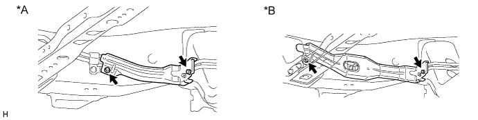
Text in Illustration *A for 1GR-FE *B for 1KD-FTV Note
When replacing the front No. 1 stabilizer control tube assembly, do not install the front stabilizer control tube insulator as it becomes unnecessary.
-
-
DISCONNECT FRONT NO. 1 STABILIZER CONTROL TUBE ASSEMBLY
-
When disconnecting the front No. 1 stabilizer control tube assembly before replacement:
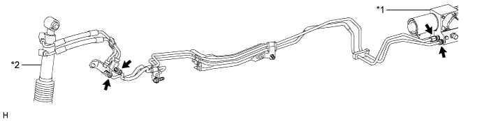
Text in Illustration *1 Stabilizer Control with Accumulator Housing Assembly *2 Front Stabilizer with Tube Cylinder Assembly
-
Using a union nut wrench, disconnect the 2 flare nuts from the stabilizer control with accumulator housing.
-
Using a union nut wrench, disconnect the 2 flare nuts from the front stabilizer with tube cylinder assembly.
-
-
When disconnecting the front No. 1 stabilizer control tube assembly after replacement:
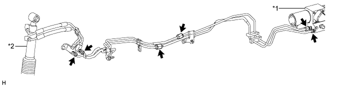
Text in Illustration *1 Stabilizer Control with Accumulator Housing Assembly *2 Front Stabilizer with Tube Cylinder Assembly
-
Using a union nut wrench, disconnect the 2 flare nuts from the stabilizer control with accumulator housing.
-
Using a union nut wrench, disconnect the 2 flare nuts from the front stabilizer with tube cylinder assembly.
-
Using a union nut wrench, disconnect the 2 flare nuts.
-
-
-
REMOVE FRONT NO. 1 STABILIZER CONTROL TUBE ASSEMBLY
-
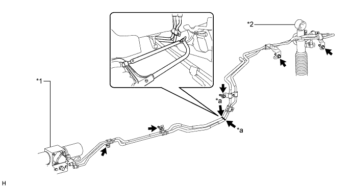
When removing the front No. 1 stabilizer control tube assembly before replacement:
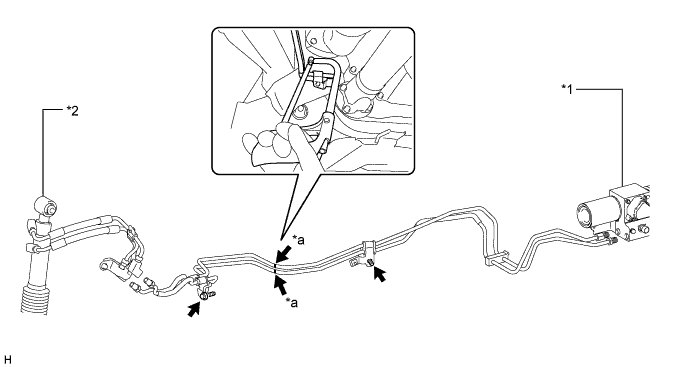
Text in Illustration *1 Stabilizer Control with Accumulator Housing Assembly *2 Front Stabilizer with Tube Cylinder Assembly *a Cut position - -
-
Using a hacksaw, cut the front No. 1 stabilizer control tube assembly at the position shown in the illustration.
CAUTION:
-
Do not cut your fingers, etc.
-
Wear protective goggles.
Note
-
Wrap protective tape around the cut ends of the front No. 1 stabilizer control tube assembly.
-
Use a piece of cloth to protect the body from becoming damaged.
-
-
Remove the bolt and front No. 1 stabilizer control tube assembly (stabilizer control with accumulator housing assembly side).
-
Remove the bolt and front No. 1 stabilizer control tube assembly (front stabilizer with tube cylinder assembly side).
Note
Make sure that the drive shaft boot is not damaged during removal.
-
-
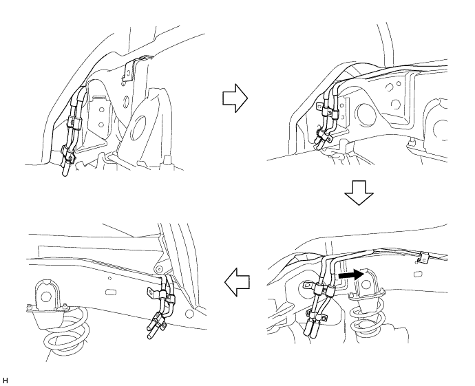
When removing the front No. 1 stabilizer control tube assembly after replacement:
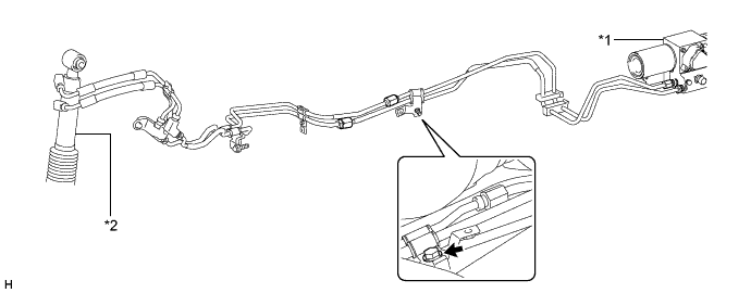
Text in Illustration *1 Stabilizer Control with Accumulator Housing Assembly *2 Front Stabilizer with Tube Cylinder Assembly
-
Remove the bolt and front No. 1 stabilizer control tube assembly (stabilizer control with accumulator housing assembly side).
-
Remove the bolt (labeled A) and clamp from the front No. 1 stabilizer control tube assembly.
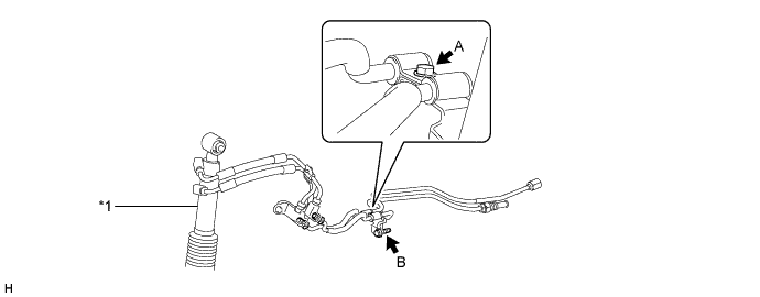
Text in Illustration *1 Front Stabilizer with Tube Cylinder Assembly - - -
Remove the bolt (labeled B), and then disconnect the front No. 1 stabilizer control tube assembly (front stabilizer with tube cylinder assembly side).
-
Remove the front No. 1 stabilizer control tube assembly (lower part) and front No. 1 stabilizer control tube assembly (upper part).
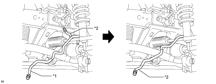
Text in Illustration *1 Front No. 1 Stabilizer Control Tube Assembly (Upper Part) *2 Front No. 1 Stabilizer Control Tube Assembly (Lower Part)
-
-
-
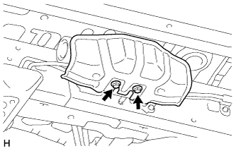
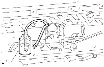
REMOVE FUEL PUMP CONTROL ECU ASSEMBLY
-
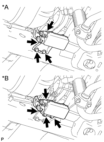
Text in Illustration *A w/o Air Suspension *B w/ Air Suspension Disconnect the 2 connectors.
-
Remove the 2 bolts and fuel pump ECU.
Note
Make sure the fuel pump ECU is not subjected to physical shocks, such as being dropped, etc.
-
-
REMOVE REAR SHOCK ABSORBER ASSEMBLY LH
-
DISCONNECT REAR NO. 1 STABILIZER CONTROL TUBE ASSEMBLY
-
When disconnecting the rear No. 1 stabilizer control tube assembly before replacement:
-
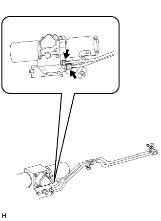
Using a union nut wrench, disconnect the 2 flare nuts from the stabilizer control with accumulator housing.
-
Remove the 2 union bolts of the rear stabilizer control cylinder and the 2 pressure port gaskets.
-
-
When disconnecting the rear No. 1 stabilizer control tube assembly after replacement:
-
Using a union nut wrench, disconnect the 2 flare nuts from the stabilizer control with accumulator housing.
-
Using a union nut wrench, disconnect the 2 flare nuts.
-
Remove the 2 union bolts of the rear stabilizer control cylinder and the 2 pressure port gaskets.
-
-
-
REMOVE REAR NO. 1 STABILIZER CONTROL TUBE ASSEMBLY
-
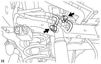
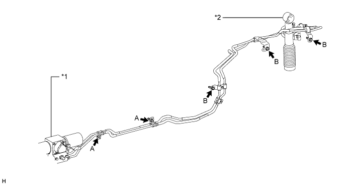
When removing the rear No. 1 stabilizer control tube assembly before replacement:
Text in Illustration *1 Stabilizer Control with Accumulator Housing Assembly *2 Rear Stabilizer Control Cylinder *a Cut position - -
-
Remove the 5 bolts and disconnect the rear No. 1 stabilizer control tube assembly.
-
Using a hacksaw, cut the rear No. 1 stabilizer control tube assembly at the position shown in the illustration.
CAUTION:
-
Do not cut your fingers, etc.
-
Wear protective goggles.
Note
-
Cut the rear No. 1 stabilizer control tube assembly while securely holding down the cut position.
-
Use a piece of cloth to protect the body from becoming damaged.
-
Wrap protective tape around the cut ends of the rear No. 1 stabilizer control tube assembly.
-
-
Remove the cut rear No. 1 stabilizer control tube assembly (stabilizer control with accumulator housing assembly side).
-
Using a plastic-faced hammer, lightly tap the cut rear No. 1 stabilizer control tube assembly (rear stabilizer control cylinder side) while sliding it to the right to remove it.
Tech Tips
Performing this procedure with 2 persons may make the removal easier.
-
-
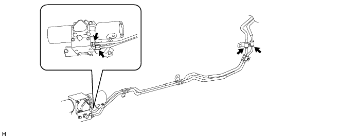
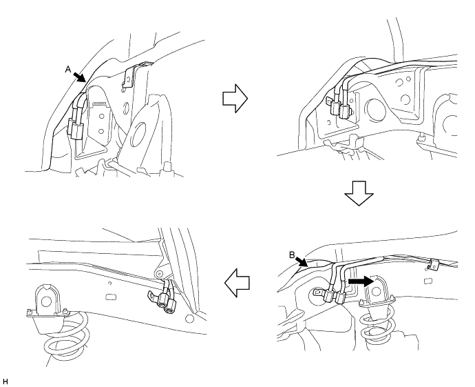
When removing the rear No. 1 stabilizer control tube assembly after replacement:
Text in Illustration *1 Stabilizer Control with Accumulator Housing Assembly *2 Rear Stabilizer Control Cylinder
-
Remove the 2 bolts (labeled A) and disconnect the rear No. 1 stabilizer control tube assembly (stabilizer control with accumulator housing assembly side).
-
Remove the 3 bolts (labeled B) and disconnect the rear No. 1 stabilizer control tube assembly (rear stabilizer control cylinder side).
-
Using a plastic-faced hammer, lightly tap the rear No. 1 stabilizer control tube assembly (rear stabilizer control cylinder side) while sliding it to the right to remove it.
Note
Make sure that the rear No. 1 stabilizer control tube assembly is not deformed, as the gaps shown by arrows A and B in the illustration are small.
Tech Tips
Performing this procedure with 2 persons may make the removal easier.
-
-