KINETIC DYNAMIC SUSPENSION SYSTEM, Diagnostic DTC:C1851/51, C1853/53

| DTC Code | DTC Name |
|---|---|
| C1851/51 | Low Pressure Malfunction in Upside of KDSS System |
| C1853/53 | High Pressure Malfunction in Upside of KDSS System |
DESCRIPTION
In the KDSS hydraulic circuit, the fluid is contained under pressure. If the fluid temperature is 20°C (68°F), the pressure is approximately 3.0 MPa (30.6 kgf/cm2, 435 psi).
| DTC Code | DTC Detection Condition | Trouble Area |
|---|---|---|
| C1851/51 | The sensor output is 0.9 MPa (9.2 kgf/cm2, 130 psi) or less for 5 min. continuously with the ignition switch ON. |
|
| C1853/53 | The sensor output is 8.8 MPa (89.7 kgf/cm2, 1276 psi) or more for 20 sec. continuously with the ignition switch ON. |
INSPECTION PROCEDURE
Tech Tips
-
When these DTCs are output, perform the hydraulic circuit inspection first Click here.
-
If the DTCs cannot be cleared even after the hydraulic circuit inspection, perform the electrical circuit inspection by following the procedures below.
PROCEDURE
-
INSPECT FOR FLUID LEAK
-
Inspect for fluid leaks Click here.
OK No fluid leaks.
NG 
REPAIR FLUID LEAK OR REPLACE PARTS AS NECESSARY
OK 
-
-
CHECK ANY OTHER DTCS OUTPUT (DTC C1812/12, C1831/31 AND/OR C1832/32)
-
Check if DTC C1812/12, C1831/31 and/or C1832/32 is output Click here.
Result Result Proceed to No output A DTC C1812/12, C1831/31 and/or C1832/32 is output B
B
REPAIR CIRCUITS INDICATED BY OUTPUT DTCS Click here
A
-
-
INSPECT STABILIZER CONTROL SOLENOID VALVE (CHECK IF VALVE STUCK)
-
Disconnect the Stabilizer control with accumulator housing assembly connector.
-
Check for an operating sound of the Stabilizer control solenoid valve.
-
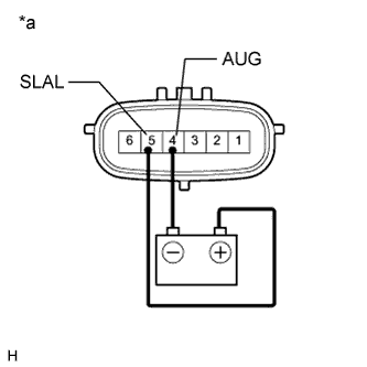
Text in Illustration *a Component without harness connected
(Stabilizer Control with Accumulator Housing Assembly)
for Upper Chamber:
Connect terminal 5 (SLAL) to the positive (+) battery terminal, and terminal 4 (AUG) to the negative (-) battery terminal.
OK An operating sound (click sound) can be heard. -
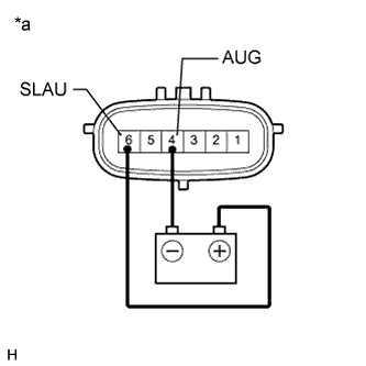
Text in Illustration *a Component without harness connected
(Stabilizer Control with Accumulator Housing Assembly)
for Lower Chamber:
Connect terminal 6 (SLAU) to the positive (+) battery terminal, and terminal 4 (AUG) to the negative (-) battery terminal.
OK An operating sound (click sound) can be heard.
-
NG
REPLACE STABILIZER CONTROL WITH ACCUMULATOR HOUSING ASSEMBLY Click here
OK
-
-
INSPECT FOR CLOGS IN HYDRAULIC CIRCUIT
-
Bleed air and check that the hydraulic circuit is not clogged Click here.
OK Hydraulic circuit is not clogged.
NG
REPAIR HYDRAULIC CIRCUIT MALFUNCTIONS OR REPLACE PARTS AS NECESSARY
OK
-
-
RECONFIRM DTC
-
Clear the DTCs Click here.
-
Check for DTCs Click here.
Result Result Proceed to DTC is not output A DTC is output B
B
REPLACE STABILIZER CONTROL ECU Click here
A 
USE SIMULATION METHOD TO CHECK Click here
-