AIR SUSPENSION SYSTEM, Diagnostic DTC:C1791/91

| DTC Code | DTC Name |
|---|---|
| C1791/91 | Adaptive Variable Suspension (AVS) Switch Circuit (Test Mode DTC) |
DESCRIPTION
The absorber control switch is used to select the damping force mode of the shock absorber.
| DTC Code | DTC Detection Condition | Trouble Area |
|---|---|---|
| C1791/91 | The absorber control switch signal does not change. |
|
Tech Tips
This DTC is stored only during test mode.
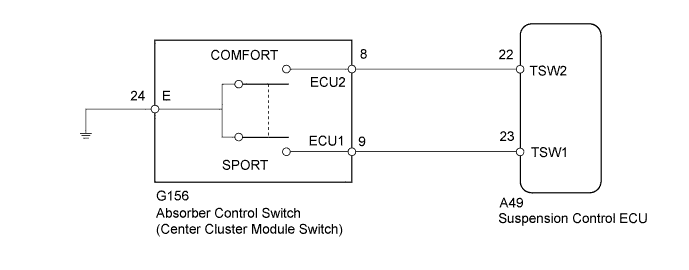
WIRING DIAGRAM
INSPECTION PROCEDURE
Note
When replacing the suspension control ECU, perform registration Click here.
PROCEDURE
-
READ VALUE USING INTELLIGENT TESTER (DAMPING CONTROL SWITCH)
-
Turn the ignition switch off.
-
Connect the intelligent tester to the DLC3.
-
Turn the ignition switch to ON.
-
Turn the intelligent tester on.
-
Enter the following menus: Chassis / Air suspension / Data List.
Air Suspension Tester Display Measurement Item/Range Normal Condition Diagnostic Note Damping Control Switch Absorber control switch /
NORMAL, COMFORT or SPORT
Indicates current absorber control switch position - -
Check that the value displayed on the intelligent tester changes by operating the absorber control switch between COMF, NORMAL and SPORT.
OK Absorber control switch value changes.
NG 
INSPECT CENTER CLUSTER MODULE SWITCH Click here
OK 
USE SIMULATION METHOD TO CHECK Click here
-
-
INSPECT CENTER CLUSTER MODULE SWITCH
-
Turn the ignition switch off.
-
Remove the absorber control switch (center cluster module switch) Click here.
-
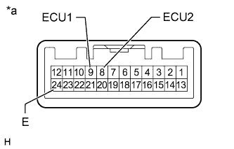
Text in Illustration *a Component without harness connected
(Absorber Control Switch (Center Cluster Module Switch))
Measure the resistance according to the value(s) in the table below.
Standard Resistance Tester Connection Switch Condition Specified Condition 24 (E) - 9 (ECU1) SPORT position Below 1 Ω Normal position 10 kΩ or higher 24 (E) - 8 (ECU2) COMF position Below 1 Ω Normal position 10 kΩ or higher
NG 
REPLACE CENTER CLUSTER MODULE SWITCH Click here
OK 
-
-
CHECK HARNESS AND CONNECTOR (CENTER CLUSTER MODULE SWITCH - SUSPENSION CONTROL ECU)
-
Disconnect the G156 absorber control switch (center cluster module switch) connector.
-
Disconnect the A49 suspension control ECU connector.
-
Measure the resistance according to the value(s) in the table below.
Standard Resistance Tester Connection Condition Specified Condition G156-9 (ECU1) - A49-23 (TSW1) Always Below 1 Ω G156-8 (ECU2) - A49-22 (TSW2) Always Below 1 Ω G156-24 (E) - Body ground Always Below 1 Ω G156-9 (ECU1) or A49-23 (TSW1) - Body ground Always 10 kΩ or higher G156-8 (ECU2) or A49-22 (TSW2) - Body ground Always 10 kΩ or higher
NG
REPAIR OR REPLACE HARNESS OR CONNECTOR
OK
REPLACE SUSPENSION CONTROL ECU Click here
-