AIR SUSPENSION SYSTEM, Diagnostic DTC:C1784/84

| DTC Code | DTC Name |
|---|---|
| C1784/84 | Steering Sensor Signal Malfunction |
DESCRIPTION
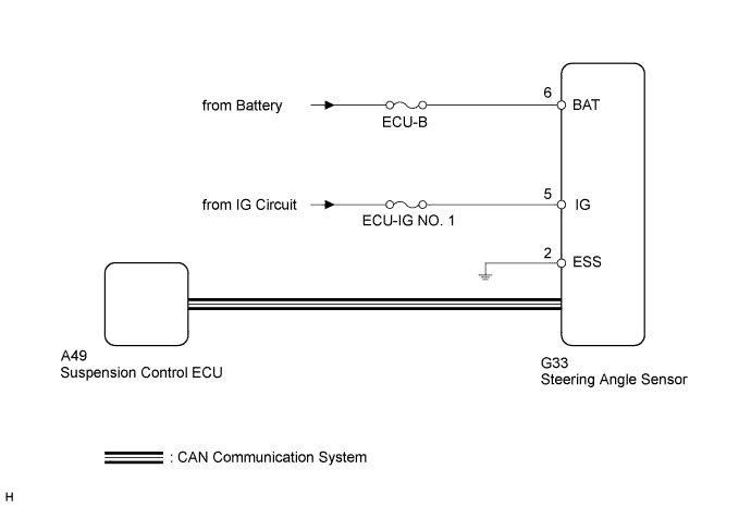
The steering angle sensor signal is sent to the suspension control ECU through CAN communication system. When there is a communication malfunction, this DTC is detected by the diagnosis function.
| DTC Code | DTC Detection Condition | Trouble Area |
|---|---|---|
| C1784/84 | A steering angle sensor signal malfunction is detected, or a steering angle sensor power source malfunction signal is detected for 5 seconds or more. |
|
WIRING DIAGRAM
INSPECTION PROCEDURE
Note
-
When replacing the suspension control ECU, perform registration Click here.
-
Inspect the fuses for circuits related to this system before performing the following inspection procedure.
-
Do not remove the steering angle sensor from the spiral cable sub-assembly.
-
When replacing the spiral cable sub-assembly, confirm that the replacement part is of the correct specification.
Tech Tips
If DTC C1782/82 is output at the same time as C1784/84, perform troubleshooting for C1782/82 first Click here.
PROCEDURE
-
CHECK DTC
-
Clear the DTCs Click here.
-
Perform a road test.
-
Check if DTCs C1784/84 and U0126/71 are output Click here.
Result Condition Proceed to DTC is not output or only DTC 1784/84 is output A DTCs 1784/84 and U0126/71 are output B
B 
GO TO DTC U0126/71 Click here
A 
-
-
CHECK DTC (VEHICLE STABILITY CONTROL SYSTEM)
-
Check for steering angle sensor malfunction DTCs Click here.
Result Condition Proceed to DTC is not output A DTC is output B
B
GO TO VEHICLE STABILITY CONTROL SYSTEM (DIAGNOSTIC TROUBLE CODE CHART) Click here
A
-
-
CHECK TERMINAL VOLTAGE AND RESISTANCE (IG, BAT, ESS)
-
Disconnect the G33 steering angle sensor connector.
-
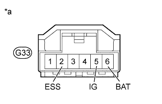
Text in Illustration *a Front view of wire harness connector
(to Steering Angle Sensor)
Measure the voltage and resistance according to the value(s) in the table below.
Standard Voltage Tester Connection Condition Specified Condition G33-5 (IG) - Body ground Ignition switch ON 11 to 14 V G33-6 (BAT) - Body ground Always 11 to 14 V Standard Resistance Tester Connection Condition Specified Condition G33-2 (ESS) - Body ground Always Below 1 Ω -
Check that the steering angle sensor connector is not deformed or corroded.
OK No deformation or corrosion. Tech Tips
If the steering angle sensor connector is defective, replace the spiral cable sub-assembly.
NG
REPAIR OR REPLACE HARNESS OR CONNECTOR
OK
-
-
READ VALUE USING INTELLIGENT TESTER (STEERING ANGLE)
-
Turn the ignition switch off.
-
Connect the intelligent tester to the DLC3.
-
Turn the ignition switch to ON.
-
Turn the intelligent tester on.
-
Enter the following menus: Chassis / Air suspension / Data List.
Air Suspension Tester Display Measurement Item/Range Normal Condition Diagnostic Note Steering Angle Steering angle/
Min.: -49152.0 deg
Max.: 49150.5 deg
Actual steering angle
Turned left: reading increases
Turned right: reading decreases
- OK Steering wheel turning angle value changes when steering wheel is turned.
NG
REPLACE SPIRAL CABLE SUB-ASSEMBLY Click here
OK 
REPLACE SUSPENSION CONTROL ECU Click here
-