AIR SUSPENSION SYSTEM, Diagnostic DTC:C1782/82

| DTC Code | DTC Name |
|---|---|
| C1782/82 | Low Battery Positive Voltage |
DESCRIPTION
| DTC Code | DTC Detection Condition | Trouble Area |
|---|---|---|
| C1782/82 | The voltage at terminal IG or B is 10 V or less or 16 V or higher for 0.5 seconds. |
|
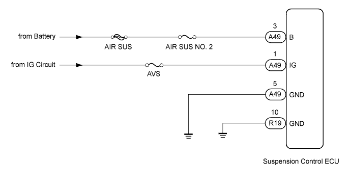
WIRING DIAGRAM
INSPECTION PROCEDURE
Note
-
When replacing the suspension control ECU, perform registration Click here.
-
Inspect the fuses for circuits related to this system before performing the following inspection procedure.
PROCEDURE
-
READ VALUE USING INTELLIGENT TESTER (IG/+B POWER SOURCE VOLTAGE)
-
Turn the ignition switch off.
-
Connect the intelligent tester to the DLC3.
-
Turn the ignition switch to ON.
-
Turn the intelligent tester on.
-
Enter the following menus: Chassis / Air suspension / Data List.
Air Suspension Tester Display Measurement Item/Range Normal Condition Diagnostic Note IG Power Source Voltage Actual ECU power supply voltage / Min.: 0.0 V, Max.: 25.5 V Ignition switch ON: 11 to 14 V - +B Power Source Voltage Actual battery supply voltage / Min.: 0.0 V, Max.: 25.5 V Ignition switch ON: 11 to 14 V - Standard voltage 11 to 14 V Result Result Proceed to NG A OK (When troubleshooting according to problem symptoms table) B OK (When troubleshooting according to DTC chart) C
B 
PROCEED TO NEXT SUSPECTED AREA SHOWN IN PROBLEM SYMPTOMS TABLE Click here
C
USE SIMULATION METHOD TO CHECK Click here
A 
-
-
CHECK TERMINAL VOLTAGE (IG, B)
-
Disconnect the A49 suspension control ECU connector.
-
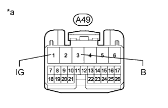
Text in Illustration *a Front view of wire harness connector
(to Suspension Control ECU)
Measure the voltage according to the value(s) in the table below.
Standard Voltage Tester Connection Condition Specified Condition A49-3 (B) - Body ground Always 11 to 14 V A49-1 (IG) - Body ground Ignition switch ON 11 to 14 V
NG
REPAIR OR REPLACE HARNESS OR CONNECTOR
OK
-
-
CHECK HARNESS AND CONNECTOR (SUSPENSION CONTROL ECU - BODY GROUND)
-
Disconnect the A49 and R19 suspension control ECU connectors.
-
Measure the resistance according to the value(s) in the table below.
Standard Resistance Tester Connection Condition Specified Condition R19-10 (GND) - Body ground Always Below 1Ω A49-5 (GND) - Body ground Always Below 1Ω
NG
REPAIR OR REPLACE HARNESS OR CONNECTOR
OK
-
-
CHECK FOR DTC
-
Clear the DTCs Click here.
-
Check for DTCs Click here.
Result Result Proceed to DTC is not output A DTC is output B
B
REPLACE SUSPENSION CONTROL ECU Click here
A 
USE SIMULATION METHOD TO CHECK Click here
-