KINETIC DYNAMIC SUSPENSION SYSTEM, Diagnostic DTC:C1812/12

| DTC Code | DTC Name |
|---|---|
| C1812/12 | Pressure Sensor Malfunction / Upside |
DESCRIPTION
In the KDSS hydraulic circuit, the fluid is contained under pressure. If the fluid temperature is 20°C (68°F), the pressure is approximately 3.0 MPa (30.6 kgf/cm2, 435 psi).
| DTC Code | DTC Detection Condition | Trouble Area |
|---|---|---|
| C1812/12 | One of the following conditions continues is met:
|
|
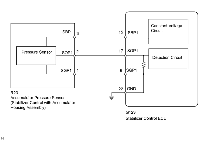
WIRING DIAGRAM
INSPECTION PROCEDURE
PROCEDURE
-
READ VALUE USING INTELLIGENT TESTER (OIL PRESSURE SENSOR)
Note
-
Perform the inspection on a level surface.
-
Perform the inspection with the vehicle empty.
-
Make sure that the wheels are on the ground and facing straight ahead.
-
Perform the inspection with the vehicle load completely on the suspension.
-
Turn the ignition switch off.
-
Connect the intelligent tester to the DLC3.
-
Turn the ignition switch to ON.
-
Turn the intelligent tester on.
-
Enter the following menus: Chassis / KDSS / Data List.
-
Select the item below in the Data List, and read the value displayed on the intelligent tester.
KDSS Tester Display Measurement Item/Range Normal Condition Diagnostic Note Oil Pressure Sensor Oil pressure sensor/
Min.: -784.79 MPa (-8002.66 kgf/cm2, -113794.55 psi)
Max.: 784.76 MPa (8002.35 kgf/cm2, 113790.20 psi)
2.6 MPa (26.5 kgf/cm2, 377 psi) to 3.0 MPa (30.6 kgf/cm2, 435 psi): When vehicle stopped and fluid temperature 20°C (68°F)
- -
Check the fluid pressure.
OK 2.6 MPa (26.5 kgf/cm2, 377 psi) to 3.0 MPa (30.6 kgf/cm2, 435 psi)
NG 
INSPECT STABILIZER CONTROL ECU (SBP1 VOLTAGE) Click here
OK 
-
-
RECONFIRM DTC
-
Clear the DTCs Click here.
-
Check for DTCs Click here.
Result Result Proceed to DTC is output A DTC is not output B
B 
USE SIMULATION METHOD TO CHECK Click here
A 
REPLACE STABILIZER CONTROL ECU Click here
-
-
INSPECT STABILIZER CONTROL ECU (SBP1 VOLTAGE)
-
Connect the stabilizer control ECU connector.
-
Disconnect the Stabilizer control with accumulator housing connector.
-
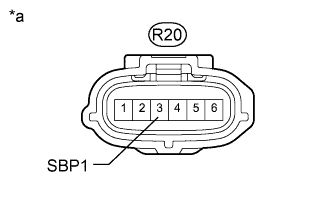
Text in Illustration *a Front view of wire harness connector
(to Stabilizer Control with Accumulator Housing Assembly)
Measure the voltage according to the value(s) in the table below.
Standard Voltage Tester Connection Switch Condition Specified Condition R20-3 (SBP1) - Body ground Ignition switch ON 4.75 to 5.25 V
NG
CHECK HARNESS AND CONNECTOR (STABILIZER CONTROL ECU - ACCUMULATOR PRESSURE SENSOR) Click here
OK
-
-
CHECK HARNESS AND CONNECTOR (STABILIZER CONTROL ECU - ACCUMULATOR PRESSURE SENSOR)
-
Disconnect the Stabilizer control ECU connector.
-
Disconnect the Stabilizer control with accumulator housing connector.
-
Measure the resistance according to the value(s) in the table below.
Standard Resistance Tester Connection Condition Specified Condition G123-17 (SOP1) - R20-2 (SOP1) Always Below 1 Ω G123-17 (SOP1) - Body ground Always 10 kΩ or higher G123-6 (SGP1) - R20-1 (SGP1) Always Below 1 Ω G123-6 (SGP1) - Body ground Always 10 kΩ or higher
NG
REPAIR OR REPLACE HARNESS OR CONNECTOR
OK
-
-
INSPECT ACCUMULATOR PRESSURE SENSOR (OUTPUT VOLTAGE)
-
Connect the stabilizer control ECU connector.
-
Connect the Stabilizer control with accumulator housing connector.
-
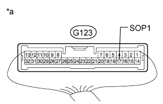
Text in Illustration *a Component with harness connected
(Stabilizer Control ECU)
Measure the voltage according to the value(s) in the table below.
Standard Voltage Tester Connection Switch Condition Specified Condition G123-17 (SOP1) - Body ground Ignition switch ON 0.4 to 4.6 V
NG
READ VALUE USING INTELLIGENT TESTER (OIL PRESSURE SENSOR) Click here
OK
REPLACE STABILIZER CONTROL ECU Click here
-
-
READ VALUE USING INTELLIGENT TESTER (OIL PRESSURE SENSOR)
-
Disconnect the Stabilizer control with accumulator housing connector.
-
Connect the stabilizer control ECU connector.
-
Connect the intelligent tester to the DLC3.
-
Turn the ignition switch to ON.
-
Turn the intelligent tester on.
-
Enter the following menus: Chassis / KDSS / Data List.
-
Select the item below in the Data List, and read the value displayed on the intelligent tester.
KDSS Tester Display Measurement Item/Range Normal Condition Diagnostic Note Oil Pressure Sensor Oil pressure sensor/
Min.: -784.79 MPa (-8002.66 kgf/cm2, -113794.55 psi)
Max.: 784.76 MPa (8002.35 kgf/cm2, 113790.20 psi)
2.6 MPa (26.5 kgf/cm2, 377 psi) to 3.0 MPa (30.6 kgf/cm2, 435 psi): When vehicle stopped and fluid temperature 20°C (68°F)
- -
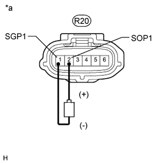
Text in Illustration *a Front view of wire harness connector
(to Stabilizer Control with Accumulator Housing Assembly)
Using a 1.5 V dry cell battery, connect the positive (+) lead to terminal 2 (SOP1) of the stabilizer control with accumulator housing connector and the negative (-) lead to terminal 1 (SGP1), and check that the Data List display changes.
OK Data List display changes.
NG
REPLACE STABILIZER CONTROL ECU Click here
OK
REPLACE STABILIZER CONTROL WITH ACCUMULATOR HOUSING ASSEMBLY Click here
-
-
CHECK HARNESS AND CONNECTOR (STABILIZER CONTROL ECU - ACCUMULATOR PRESSURE SENSOR)
-
Disconnect the Stabilizer control ECU connector.
-
Disconnect the Stabilizer control with accumulator housing connector.
-
Measure the resistance according to the value(s) in the table below.
Standard Resistance Tester Connection Condition Specified Condition G123-15 (SBP1) - R20-3 (SBP1) Always Below 1 Ω G123-15 (SBP1) - Body ground Always 10 kΩ or higher
NG
REPAIR OR REPLACE HARNESS OR CONNECTOR
OK
REPLACE STABILIZER CONTROL ECU Click here
-