REAR AXLE SHAFT INSTALLATION

Tech Tips
-
Use the same procedure for the RH and LH sides.
-
The procedure listed below is for the LH side.
-
INSTALL REAR AXLE SHAFT OIL SEAL LH
-
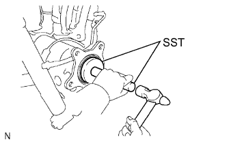
Using SST and a hammer, install a new axle shaft oil seal.
- SST
- 09950-60020 ( 09951-00770 )
- 09950-70010 ( 09951-07150 )
Note
Do not allow foreign matter, etc. to contact the axle shaft housing hole.
-
-
INSTALL REAR AXLE SHAFT WITH PARKING BRAKE PLATE LH
-
Install a new O-ring to the axle housing.
-
Install the rear axle shaft with parking brake plate with the 4 nuts.
- Torque:
- 60 N*m { 612 kgf*cm, 44 ft.*lbf }
-
-
INSTALL PARKING BRAKE ASSEMBLY
-
Install the parking brake assembly Click here.
-
-
INSTALL REAR SPEED SENSOR LH
-
Install the speed sensor with the nut.
- Torque:
- 7.8 N*m { 80 kgf*cm, 69 in.*lbf }
Note
-
Make sure there are no pieces of iron or other foreign matter attached to the sensor tip.
-
While inserting the speed sensor into the axle hole, do not strike or damage the sensor tip.
-
After installing the speed sensor, make sure there is no clearance or foreign matter between the sensor stay part and the axle.
-
Make sure there is no foreign matter attached to the speed sensor rotor.
-
Connect the speed sensor connector.
Note
Securely connect the connector.
-
-
CONNECT REAR FLEXIBLE HOSE LH
-
Connect the rear flexible hose to the connecting point with the brake tube, and then install a new clip.
-
Using a union nut wrench, connect the brake tube to the rear flexible hose while holding the rear flexible hose with a wrench.
- Torque:
- 15 N*m { 155 kgf*cm, 11 ft.*lbf }
Note
-
Do not bend or damage the brake tube.
-
Do not allow any foreign matter such as dirt and dust to enter the brake tube from the connecting point.
-
Use the formula to calculate special torque values for situations where a union nut wrench is combined with a torque wrench Click here.
-
Install the rear flexible hose and a new gasket to the rear disc brake cylinder with the new union bolt.
- Torque:
- 31 N*m { 316 kgf*cm, 23 ft.*lbf }
Tech Tips
Install the flexible hose lock securely to the lock hole in the cylinder.
-
-
FILL RESERVOIR WITH BRAKE FLUID
-
BLEED BRAKE LINE
-
for Hydraulic Brake Booster:
Bleed the brake line Click here.
-
for Vacuum Brake Booster:
Bleed the brake line Click here.
-
-
CHECK BRAKE FLUID LEVEL IN RESERVOIR
-
for Hydraulic Brake Booster:
Check the brake fluid level in reservoir Click here.
-
for Vacuum Brake Booster:
Check the brake fluid level in reservoir Click here.
-
-
INSPECT FOR BRAKE FLUID LEAK
-
CONNECT CABLE TO NEGATIVE BATTERY TERMINAL
Note
When disconnecting the cable, some systems need to be initialized after the cable is reconnected Click here.
-
INSTALL REAR WHEEL
- Torque:
- 112 N*m { 1142 kgf*cm, 83 ft.*lbf }
-
INSPECT PARKING BRAKE PEDAL TRAVEL
-
Fully pull the parking brake lever to engage the parking brake.
-
Release the lever to disengage the parking brake.
-
Slowly pull the parking brake lever all the way and count the number of clicks.
Standard parking brake lever travel when pulled with a force of 200 N (20 kgf, 45 lbf) 5 to 7 clicks If the parking brake lever travel is not as specified, adjust the parking brake shoe clearance and parking brake lever travel.
-
-
CHECK SPEED SENSOR SIGNAL
-
for VSC (Hydraulic Brake Booster):
-
for VSC (Vacuum Brake Booster):
-
for ABS:
-