STEERING KNUCKLE INSTALLATION

Tech Tips
-
Use the same procedure for the RH and LH sides.
-
The procedure listed below is for the LH side.
-
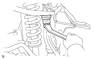
INSTALL STEERING KNUCKLE LH
-
Install the steering knuckle to the front suspension upper arm with the nut.
- Torque:
- 110 N*m { 1122 kgf*cm, 82 ft.*lbf }
-
Install a new clip.
-
-
INSTALL FRONT LOWER BALL JOINT ATTACHMENT LH
-
Install the front lower ball joint attachment with the 2 bolts.
- Torque:
- 160 N*m { 1632 kgf*cm, 118 ft.*lbf }
-
-
CONNECT TIE ROD END SUB-ASSEMBLY LH
-
Connect the tie rod end to the steering knuckle with the nut.
- Torque:
- 91 N*m { 928 kgf*cm, 67 ft.*lbf }
Note
Tighten the nut up to an additional 60° if the holes for the cotter pin are not aligned.
-
Install a new cotter pin.
-
-
INSTALL FRONT AXLE HUB SUB-ASSEMBLY LH
-
Install the front axle hub Click here.
-
-
INSTALL FRONT SPEED SENSOR LH
-
Install the speed sensor with the bolt.
- Torque:
- 8.5 N*m { 87 kgf*cm, 75 in.*lbf }
Note
-
Make sure there are no pieces of iron or other foreign matter attached to the sensor tip.
-
While inserting the speed sensor into the knuckle hole, do not strike or damage the sensor tip.
-
After installing the speed sensor, make sure there is no clearance or foreign matter between the sensor stay part and the knuckle.
-
Make sure there is no foreign matter attached to the speed sensor rotor.
-
-
CONNECT CABLE TO NEGATIVE BATTERY TERMINAL
Note
When disconnecting the cable, some systems need to be initialized after the cable is reconnected Click here.
-
INSTALL FRONT WHEEL
- Torque:
- 112 N*m { 1142 kgf*cm, 83 ft.*lbf }
-
INSPECT AND ADJUST FRONT WHEEL ALIGNMENT
-
Inspect and adjust the front wheel alignment Click here.
-
-
CHECK FRONT SPEED SENSOR
-
Check the front speed sensor Click here.
-