- Click here
REMOVE FRONT WHEEL
- Click here
REMOVE FRONT DISC BRAKE CYLINDER ASSEMBLY LH
-
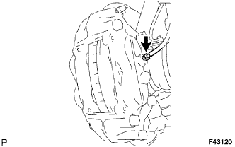
Using a union nut wrench, disconnect the brake tube from the disc brake cylinder assembly.
Tip:Use a container to catch brake fluid as it drains out.
-
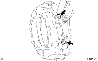
Remove the 2 bolts and disc brake cylinder assembly.
-
- Click here
REMOVE FRONT DISC
-
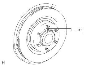
Place matchmarks on the disc and axle hub if planning to reuse the disc.
Table 1. Text in Illustration *1 Matchmark -
Remove the front disc.
-
- Click here
REMOVE FRONT AXLE HUB GREASE CAP
-
Using a screwdriver and hammer, remove the front axle hub grease cap.
Note:Do not damage the axle hub.
-
- Click here
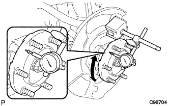
INSPECT FRONT AXLE HUB BEARING LOOSENESS
-
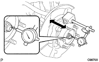
Using a dial indicator, measure the looseness near the center of the axle hub.
Maximum looseness 0.05 mm (0.00197 in.) Note:Make sure that the dial indicator is set at a right angle to the measurement surface.
If the looseness is more than the maximum, replace the axle hub.
-
- Click here
INSPECT FRONT AXLE HUB RUNOUT
-
Using a dial indicator, measure the runout on the surface of the axle hub outside the hub bolts.
Maximum runout 0.08 mm (0.00315 in.) Note:Make sure that the dial indicator is set at a right angle to the measurement surface.
If the runout is more than the maximum, replace the axle hub.
-
- Click here
INSTALL FRONT AXLE HUB GREASE CAP
-
Install a new axle hub grease cap.
Note:Make sure the grease cap is securely installed to the axle hub.
-
- Click here
INSTALL FRONT DISC
-
Align the matchmarks and install the front disc.
Tip:When replacing the disc with a new one, select the installation position where the disc has the smallest runout.
-
- Click here
INSTALL DISC BRAKE CYLINDER ASSEMBLY LH
-
Install the disc brake cylinder assembly with the 2 bolts.
123 N*m 1254 kgf*cm 91 ft.*lbf -
Using a union nut wrench, connect the brake tube to the disc brake cylinder assembly.
15 N*m 155 kgf*cm 11 ft.*lbf Note:Use the formula to calculate special torque values for situations where a union nut wrench is combined with a torque wrench (Click here).
-
- Click here
INSTALL FRONT WHEEL
112 N*m 1142 kgf*cm 83 ft.*lbf