4WD CONTROL ECU REMOVAL
-
PRECAUTION
Note
After turning the ignition switch off, waiting time may be required before disconnecting the cable from the negative (-) battery terminal. Therefore, make sure to read the disconnecting the cable from the negative (-) battery terminal notice before proceeding with work Click here.
-
DISCONNECT CABLE FROM NEGATIVE BATTERY TERMINAL
Note
When disconnecting the cable, some systems need to be initialized after the cable is reconnected Click here.
-
REMOVE DOOR SCUFF PLATE ASSEMBLY RH
Tech Tips
Use the same procedure described for the LH side.
-
REMOVE COWL SIDE TRIM BOARD RH
Tech Tips
Use the same procedure described for the LH side.
-
REMOVE INSTRUMENT SIDE PANEL RH
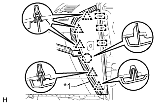
Text in Illustration *1 Protective Tape
-
Put protective tape around the instrument side panel.
-
Using a moulding remover, detach the 5 clips, claw, and 3 guides.
-
Disconnect the connector and remove the instrument side panel.
-
-
REMOVE INSTRUMENT PANEL ORNAMENT
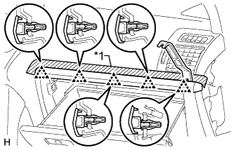
Text in Illustration *1 Protective Tape
-
Put protective tape around the instrument panel ornament.
-
Using a moulding remover, detach the 5 clips and remove the instrument panel ornament.
-
-
REMOVE NO. 2 INSTRUMENT PANEL UNDER COVER SUB-ASSEMBLY
-
Remove the screw.
-
Detach the 3 clips and 2 guides and remove the No. 2 instrument panel under cover.
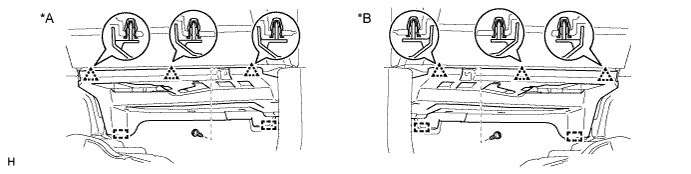
Text in Illustration *A for LHD *B for RHD
-
-
REMOVE GLOVE COMPARTMENT DOOR ASSEMBLY
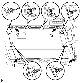
Text in Illustration *1 Bolt *2 Screw
-
Remove the 2 bolts <C> and 2 screws <A> or <B>.
-
Detach the 5 clips and claw.
-
Disconnect each connector and remove the glove compartment door.
-
-
REMOVE 4 WHEEL DRIVE CONTROL ECU
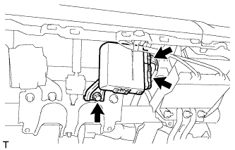
-
Disconnect the 2 connectors.
-
Remove the bolt and 4 wheel drive control ECU.
-