TRANSFER ASSEMBLY REASSEMBLY

-
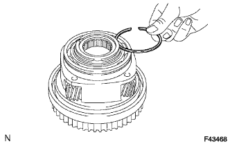
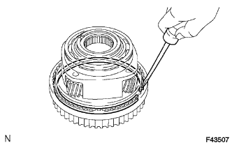
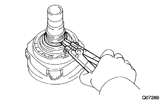
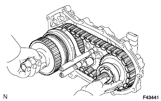
INSTALL TRANSFER LOW PLANETARY RING GEAR
-
Install the low planetary ring gear to the front transfer case.
-
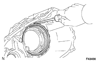
Using a screwdriver, install the snap ring.
-
-
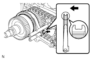
INSTALL PIN
-
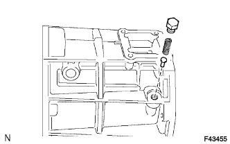
Install the pin.
-
-
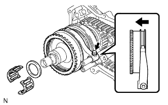
INSTALL COMPRESSION SPRING
-
Install the spring.
-
-
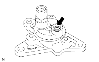
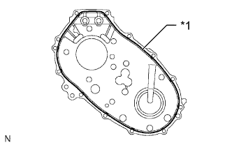
INSTALL TRANSFER CASE PLUG
-
Install the transfer case plug.
- Torque:
- 19 N*m { 190 kgf*cm, 14 ft.*lbf }
-
-
INSTALL TRANSFER OUTPUT SHAFT PLATE WASHER
-
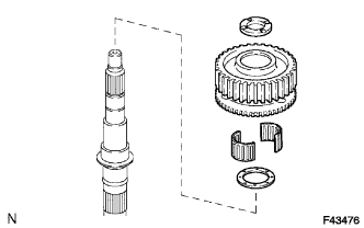
Install the washer.
-
-
INSTALL TRANSFER DRIVE SPROCKET BEARING
-
Install the bearing.
-
-
INSTALL TRANSFER DRIVE SPROCKET SUB-ASSEMBLY
-
Install the transfer drive sprocket.
-
-
INSTALL NO. 1 TRANSFER OUTPUT SHAFT SPACER
-
Install the output shaft spacer.
-
-
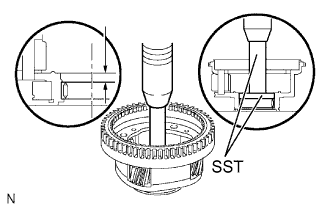
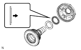
INSTALL REAR TRANSFER OUTPUT SHAFT RADIAL BALL BEARING
-
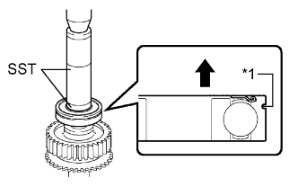
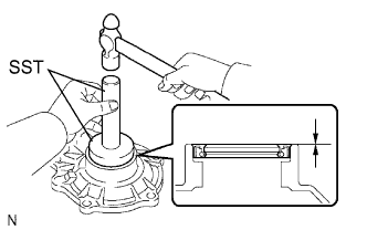
Text in Illustration *1 Groove 
Rear Using SST and a press, install a new bearing.
- SST
- 09316-60011 ( 09316-00011, 09316-00071 )
Note
Install the bearing so that the bearing snap ring groove faces the rear.
-
-
INSTALL TRANSFER OUTPUT SHAFT PLATE WASHER
-
Install the washer.
-
-
INSTALL TRANSFER OUTPUT SHAFT FRONT NEEDLE ROLLER BEARING
-
Install the needle roller bearing.
-
-
INSTALL TRANSFER CLUTCH HUB
-
Install the transfer clutch hub.
-
-
INSTALL CENTER DIFFERENTIAL CASE
-
Install the center differential case.
-
-
INSTALL TRANSFER OUTPUT SHAFT SPACER BALL
-
Install the ball.
-
-
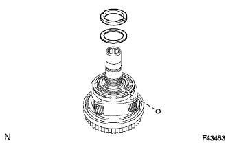
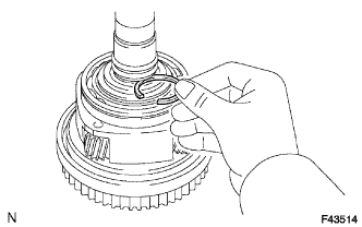
INSTALL NO. 2 TRANSFER OUTPUT SHAFT SPACER
-
Install the spacer.
-
Using a snap ring expander, install the snap ring.
-
-
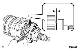
INSPECT DRIVE SPROCKET RADIAL CLEARANCE
-
Using a dial indicator, measure the radial clearance of the drive sprocket.
Standard clearance 0.01 to 0.06 mm (0.000394 to 0.0236 in.) Maximum clearance 0.06 mm (0.0236 in.) If the clearance is more than the maximum, replace the drive sprocket, rear output shaft or bearing.
-
-
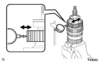
INSPECT DRIVE SPROCKET THRUST CLEARANCE
-
Using a feeler gauge, measure the thrust clearance of the drive sprocket.
Standard clearance 0.15 to 0.24 mm (0.00591 to 0.00944 in.) Maximum clearance 0.24 mm (0.00944 in.) If the clearance is more than the maximum, replace the drive sprocket.
-
-
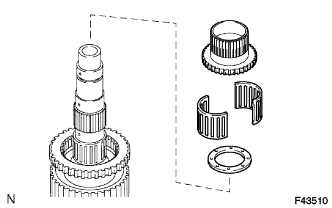
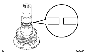
INSTALL TRANSFER INPUT SHAFT BEARING
-
Using SST and a press, install a new bearing with the groove facing forward.
- SST
- 09223-15020
- 09515-30010
- 09950-70010 ( 09951-07100 )
-
-
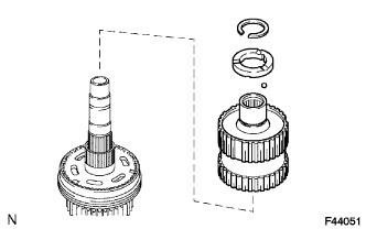
INSTALL TRANSFER INPUT BEARING SHAFT SNAP RING
-
Select a new snap ring that allows minimal axial play.
Standard Snap Ring Thickness Mark Specified Condition 1 1.45 to 1.50 mm (0.0571 to 0.0591 in.) 2 1.50 to 1.55 mm (0.0591 to 0.0610 in.) 3 1.55 to 1.60 mm (0.0610 to 0.0630 in.) 4 1.60 to 1.65 mm (0.0630 to 0.0650 in.) 5 1.65 to 1.70 mm (0.0650 to 0.0669 in.) -
Using a snap ring expander, install the snap ring.
-
-
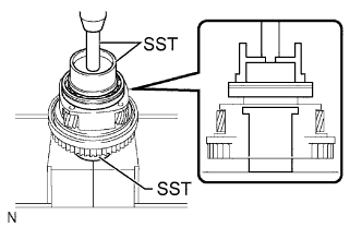
INSTALL TRANSFER LOW PLANETARY GEAR SPLINE PIECE
-
Using a screwdriver, install the low planetary gear spline piece and snap ring.
-
-
INSTALL TRANSFER LOW PLANETARY GEAR BEARING
-
Using SST and a press, press in a new low planetary gear bearing.
- SST
- 09950-60010 ( 09951-00570 )
- 09950-70010 ( 09951-07100 )
Press in depth 7.7 to 8.3 mm (0.304 to 0.326 in.)
-
-
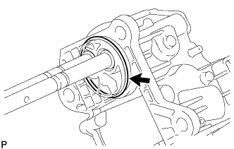
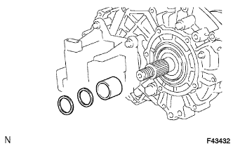
INSTALL NO. 1 TRANSFER INPUT SHAFT SEAL RING
-
Apply gear oil to 2 new seal rings.
-
Install the 2 seal rings to the input shaft.
Note
When installing the seal ring, make sure not to expand it so that its inner diameter exceeds 65 mm (2.55 in.).
-
-
INSTALL TRANSFER LOW PLANETARY GEAR THRUST BEARING
-
Install the bearing.
Text in Illustration Front
-
-
INSTALL NO. 1 TRANSFER THRUST BEARING RACE
-
Install the thrust bearing race.
-
-
INSTALL TRANSFER INPUT SHAFT
-
Install the transfer input shaft.
-
-
INSTALL MANUAL TRANSFER PLANETARY CARRIER WASHER
-
Install the washer.
-
-
INSTALL TRANSFER INPUT GEAR STOPPER BALL
-
Install the ball.
-
-
INSTALL TRANSFER INPUT GEAR STOPPER
-
Install the input gear stopper.
-
-
INSTALL TRANSFER INPUT GEAR STOPPER SHAFT SNAP RING
-
Select a new input gear stopper shaft snap ring that allows 0.05 to 0.15 mm (0.00197 to 0.00590 in.) of axial play.
Standard Snap Ring Thickness Specified Condition 2.10 to 2.15 mm (0.0827 to 0.0846 in.) 2.15 to 2.20 mm (0.0846 to 0.0866 in.) 2.20 to 2.25 mm (0.0866 to 0.0886 in.) 2.25 to 2.30 mm (0.0886 to 0.0906 in.) 2.30 to 2.35 mm (0.0906 to 0.0925 in.) 2.35 to 2.40 mm (0.0925 to 0.0945 in.) 2.40 to 2.45 mm (0.0945 to 0.0965 in.) 2.45 to 2.50 mm (0.0965 to 0.0984 in.) 2.50 to 2.55 mm (0.0984 to 0.100 in.) 2.55 to 2.60 mm (0.100 to 0.102 in.) 2.60 to 2.65 mm (0.102 to 0.104 in.) 2.65 to 2.70 mm (0.104 to 0.106 in.) 2.70 to 2.75 mm (0.106 to 0.108 in.) 2.75 to 2.80 mm (0.108 to 0.110 in.) 2.80 to 2.85 mm (0.110 to 0.112 in.) 2.85 to 2.90 mm (0.112 to 0.114 in.) 2.90 to 2.95 mm (0.114 to 0.116 in.) 2.95 to 3.00 mm (0.116 to 0.118 in.) 3.00 to 3.05 mm (0.118 to 0.120 in.) -
Using a snap ring expander, install the snap ring.
-
-
INSTALL LOW PLANETARY GEAR ASSEMBLY WITH TRANSFER INPUT SHAFT SUB-ASSEMBLY
-
Install the low planetary gear together with the input shaft.
-
Using a snap ring expander, install the shaft snap ring.
-
-
INSTALL TRANSFER OIL PUMP GEAR
-
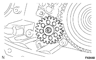
Install the transfer oil pump gear.
-
-
INSTALL TRANSFER OIL PUMP BODY O-RING
-
Coat a new O-ring with gear oil and install it to the oil pump body.
-
-
INSTALL TRANSFER OIL PUMP BODY SUB-ASSEMBLY
-
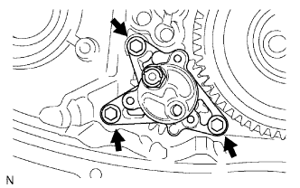
Install the oil pump body with the 3 bolts.
- Torque:
- 7.5 N*m { 76 kgf*cm, 66 in.*lbf }
-
-
INSTALL TRANSFER CASE MAGNET
-
INSTALL TRANSFER OIL SEPARATOR SUB-ASSEMBLY
-
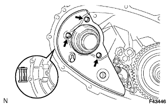
Install the oil separator with the 3 bolts.
- Torque:
- 7.5 N*m { 76 kgf*cm, 66 in.*lbf }
-
-
INSTALL FILLER PLUG
-
Install a new gasket and the filler plug.
- Torque:
- 37 N*m { 377 kgf*cm, 27 ft.*lbf }
-
-
INSTALL DRAIN PLUG
-
Install a new gasket and the drain plug.
- Torque:
- 37 N*m { 377 kgf*cm, 27 ft.*lbf }
-
-
INSTALL TRANSFER SHIFT ACTUATOR ASSEMBLY
-
Install a new O-ring to the transfer shift actuator assembly.
-
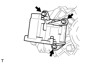
Install the transfer shift actuator assembly with the 3 bolts.
- Torque:
- 20 N*m { 204 kgf*cm, 15 ft.*lbf }
-
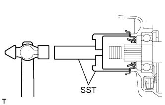
Using a screwdriver and hammer, tap on the 2 snap rings.
-
-
INSTALL TRANSFER INPUT GEAR RADIAL BALL BEARING
-
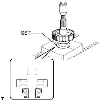
Using SST and a press, install a new input gear radial ball bearing.
- SST
- 09316-60011 ( 09316-00031 )
-
-
INSTALL TRANSFER DRIVEN SPROCKET BEARING
-
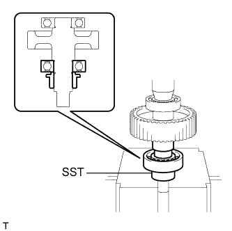
Using SST and a press, install a new driven sprocket bearing.
- SST
- 09316-60011 ( 09316-00071 )
-
-
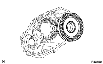
INSTALL REAR OUTPUT SHAFT SUB-ASSEMBLY, FRONT DRIVE CHAIN AND DRIVEN SPROCKET SUB-ASSEMBLY
-
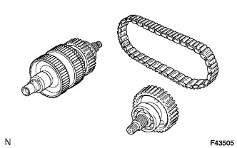
Install the rear output shaft and drive sprocket to the front drive chain.
-
Install the rear output shaft, front drive chain and driven sprocket to the rear transfer case.
Tech Tips
Check that the rear output shaft and driven sprocket turn without much effort.
-
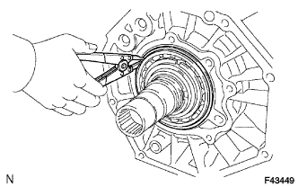
Using a snap ring expander, install the snap ring.
Note
Make sure that the snap ring is firmly installed to the groove.
-
-
INSTALL CENTER DIFFERENTIAL LOCK FORK SUB-ASSEMBLY WITH FRONT DRIVE CLUTCH SLEEVE
-
Install the center differential lock fork and front drive clutch sleeve.
Text in Illustration Front Note
Install the clutch sleeve in the correct direction.
-
Install the bolt.
- Torque:
- 24 N*m { 245 kgf*cm, 18 ft.*lbf }
-
Using a screwdriver and hammer, drive in the snap ring.
-
-
INSTALL NO. 2 TRANSFER GEAR SHIFT FORK SUB-ASSEMBLY WITH TRANSFER HIGH AND LOW CLUTCH SLEEVE
-
Install the No. 2 gear shift fork and high and low clutch sleeve.
Text in Illustration Front Note
Install the clutch sleeve in the correct direction.
-
Install the bolt.
- Torque:
- 24 N*m { 245 kgf*cm, 18 ft.*lbf }
-
-
INSTALL TRANSFER OUTPUT SHAFT FRONT NEEDLE ROLLER BEARING
-
Install the needle roller bearing to the input shaft.
-
-
INSTALL TRANSFER OUTPUT SHAFT SPACER
-
Install the transfer output shaft spacer to the input shaft.
-
-
INSTALL REAR TRANSFER CASE
-
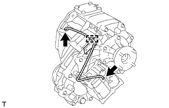
Text in Illustration *1 Seal Packing Apply seal packing to the rear transfer case as shown in the illustration.
Seal packing Toyota Genuine Seal Packing 1281, Three Bond 1281 or equivalent Note
If the removed rear transfer case is reused, be sure to perform the following before reinstalling it: 1) using a knife, cut off any old seal packing on the rear transfer case contact surface, 2) clean off any remaining old seal packing from the rear transfer case contact surface, and 3) reapply seal packing to the rear transfer case.
-
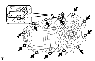
Install the clamp and rear transfer case with the 12 bolts.
- Torque:
- 28 N*m { 286 kgf*cm, 21 ft.*lbf }
Note
Tighten the bolts of the rear transfer case within 10 minutes of applying the seal packing. The seal packing will dry very quickly.
-
-
INSTALL COLLAR
-
Install the collar.
-
-
INSTALL TRANSFER OUTPUT SHAFT WASHER
-
Install the 2 washers.
-
-
INSTALL TRANSFER EXTENSION HOUSING SUB-ASSEMBLY
-
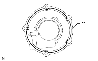
Text in Illustration *1 Seal Packing Apply seal packing to the extension housing as shown in the illustration.
Seal packing Toyota Genuine Seal Packing 1281, Three Bond 1281 or equivalent Note
If the removed extension housing is reused, be sure to perform the following before reinstalling it: 1) using a knife, cut off any old seal packing on the housing contact surface, 2) clean off any remaining old seal packing from the housing contact surface, and 3) reapply seal packing to the housing.
-
Apply adhesive to the threads of the bolts.
Adhesive Toyota Genuine Adhesive 1344, Three Bond 1344 or equivalent -
Install the extension housing with the 5 bolts.
- Torque:
- 12 N*m { 122 kgf*cm, 9 ft.*lbf }
Note
Tighten the bolts of the extension housing within 10 minutes of applying the seal packing. The seal packing will dry very quickly.
-
-
INSTALL TRANSFER CASE REAR OIL SEAL
-
Coat the lip of a new oil seal with MP grease.
-
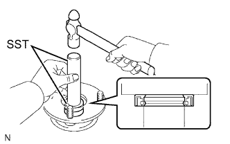
Using SST and a hammer, tap in the oil seal until its surface is flush with the case upper surface.
- SST
- 09223-46011
- 09631-32020
-
-
INSTALL REAR TRANSFER OUTPUT SHAFT COMPANION FLANGE OIL SEAL
-
Using SST and a hammer, tap in a new oil seal.
- SST
- 09950-60010 ( 09951-00320 )
- 09950-70010 ( 09951-07100 )
-
Coat the lip of the oil seal with MP grease.
-
-
INSTALL REAR OUTPUT SHAFT COMPANION FLANGE SUB-ASSEMBLY
-
Apply gear oil to the connecting areas of the companion flange and output shaft.
-
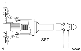
Install the companion flange to the output shaft.
Text in Illustration Rear -
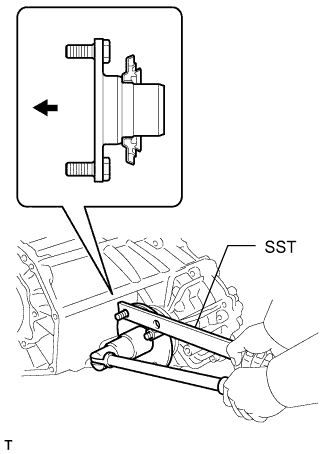
Using SST to hold the companion flange, install a new lock nut.
- SST
- 09330-00021
- Torque:
- 118 N*m { 1203 kgf*cm, 87 ft.*lbf }
-
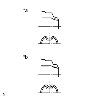
Text in Illustration *a Correct *b Incorrect Using a chisel and hammer, stake the lock nut.
Note
-
Securely stake the shaft to the lock nut groove.
-
Be careful not to damage the parts around the lock nut.
-
Do not apply excessive force to the shaft.
-
-
-
INSTALL TRANSFER CASE FRONT OIL SEAL
-
Coat the lip of a new oil seal with MP grease.
-
Using SST and a hammer, tap in the oil seal until its metal ring contacts the case.
- SST
- 09649-17010
- 09950-70010 ( 09951-07100 )
-
-
INSTALL FRONT TRANSFER OUTPUT SHAFT COMPANION FLANGE OIL SEAL
-
Using SST and a hammer, tap in a new oil seal.
- SST
- 09950-60010 ( 09951-00320 )
- 09950-70010 ( 09951-07100 )
-
Coat the lip of the oil seal with MP grease.
-
-
INSTALL FRONT OUTPUT SHAFT COMPANION FLANGE SUB-ASSEMBLY
-
Apply gear oil to the connecting areas of the companion flange and driven sprocket.
-
Install the companion flange to the driven sprocket.
Text in Illustration Front -
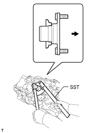
Using SST to hold the companion flange, install a new lock nut.
- SST
- 09330-00021
- Torque:
- 118 N*m { 1203 kgf*cm, 87 ft.*lbf }
-
Text in Illustration *a Correct *b Incorrect Using a chisel and hammer, stake the lock nut.
Note
-
Securely stake the shaft to the lock nut groove.
-
Be careful not to damage the parts around the lock nut.
-
Do not apply excessive force to the shaft.
-
-
-
INSTALL BREATHER OIL DEFLECTOR
-
Install the oil deflector.
-
-
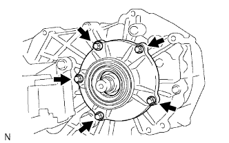
INSTALL TRANSFER CASE COVER SUB-ASSEMBLY
-
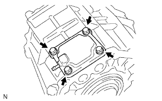
Install the case cover with the 4 bolts.
- Torque:
- 18 N*m { 184 kgf*cm, 13 ft.*lbf }
-
-
INSTALL TRANSFER BEARING RETAINER OIL SEAL RH
-
for A343F, A750F, G52F, R150F:
Using SST and a hammer, drive in a new transfer bearing retainer oil seal RH until its surface is flush with the retainer upper surface.
- SST
- 09950-60010 ( 09951-00590 )
- 09950-70010 ( 09951-07100 )
-
for RA61F:
Using SST and a hammer, tap in 2 new transfer bearing retainer oil seals RH A and B as shown in the illustration.
- SST
- 09950-60010 ( 09951-00590 )
- 09950-70010 ( 09951-07100 )
-
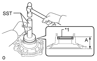
Text in Illustration *1 Oil Seal A for oil seal A:
Drive in depth (A) 43 to 44 mm (1.70 to 1.73 in.) -
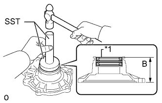
Text in Illustration *1 Oil Seal B for oil seal B:
Drive in depth (B) 53.5 to 54 mm (2.11 to 2.12 in.)
-
Coat the lip of the transfer bearing retainer oil seal RH with MP grease.
-
-
INSTALL TRANSFER BEARING RETAINER SUB-ASSEMBLY RH
-
for RA61F:
Install a new O-ring to the transfer bearing retainer sub-assembly RH.
Note
Apply MP grease to the O-ring when installing the transfer onto the transmission.
-
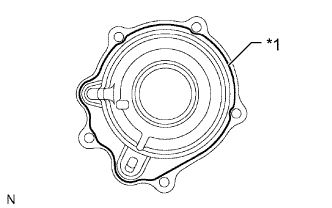
Text in Illustration *1 Seal Packing Apply seal packing to the transfer bearing retainer sub-assembly RH as shown in the illustration.
Seal packing Toyota Genuine Seal Packing 1281, Three Bond 1281 or equivalent Note
If the removed transfer bearing retainer sub-assembly RH is reused, be sure to perform the following before reinstalling it: 1) using a knife, cut off any old seal packing on the retainer contact surface, 2) clean off any remaining old seal packing from the retainer contact surface, and 3) reapply seal packing to the transfer bearing retainer sub-assembly RH.
-
Apply sealant to the bolt threads.
Sealant Toyota Genuine Adhesive 1344, Three Bond 1344 or equivalent -
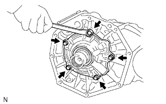
Install the transfer bearing retainer sub-assembly RH with the 5 bolts.
- Torque:
- 12 N*m { 117 kgf*cm, 8 ft.*lbf }
Note
Tighten the bolts of the transfer bearing retainer sub-assembly RH within 10 minutes of applying the seal packing. The seal packing will dry very quickly.
-
-
INSTALL HOSE
-
Attach the clamp and install the hose.
-