INPUT SHAFT DISASSEMBLY

-
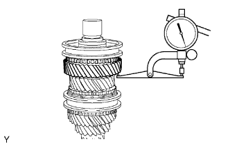
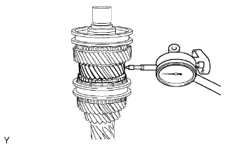
INSPECT 6TH GEAR THRUST CLEARANCE
-
Using a dial indicator, measure the 6th gear thrust clearance.
Standard clearance 0.20 to 0.49 mm (0.00788 to 0.0193 in.) If the clearance is outside the specification, replace the gear, spacer or shaft.
Tech Tips
Replace the part or parts determined to be the most likely cause of the problem.
-
-
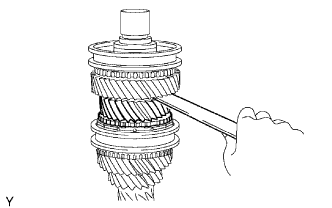
INSPECT 3RD GEAR THRUST CLEARANCE
-
Using a feeler gauge, measure the 3rd gear thrust clearance.
Standard clearance 0.09 to 0.52 mm (0.00355 to 0.0205 in.) If the clearance is outside the specification, replace the gear, thrust washer, clutch hub or shaft.
Tech Tips
Replace the part or parts determined to be the most likely cause of the problem.
-
-
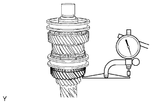
INSPECT 4TH GEAR THRUST CLEARANCE
-
Using a dial indicator, measure the 4th gear thrust clearance.
Standard clearance 0.12 to 0.38 mm (0.00473 to 0.0150 in.) If the clearance is outside the specification, replace the gear, clutch hub or shaft.
Tech Tips
Replace the part or parts determined to be the most likely cause of the problem.
-
-
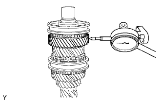
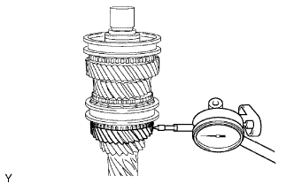
INSPECT 6TH GEAR RADIAL CLEARANCE
-
Using a dial indicator, measure the 6th gear radial clearance.
Standard clearance 0.015 to 0.065 mm (0.000591 to 0.00255 in.) If the clearance is outside the specification, replace the gear, needle roller bearing or shaft.
Tech Tips
Replace the part or parts determined to be the most likely cause of the problem.
-
-
INSPECT 3RD GEAR RADIAL CLEARANCE
-
Using a dial indicator, measure the 3rd gear radial clearance.
Standard clearance 0.015 to 0.067 mm (0.000591 to 0.00263 in.) If the clearance is outside the specification, replace the gear, needle roller bearing or shaft.
Tech Tips
Replace the part or parts determined to be the most likely cause of the problem.
-
-
INSPECT 4TH GEAR RADIAL CLEARANCE
-
Using a dial indicator, measure the 4th gear radial clearance.
Standard clearance 0.015 to 0.051 mm (0.000591 to 0.00200 in.) If the clearance is outside the specification, replace the gear, needle roller bearing or shaft.
Tech Tips
Replace the part or parts determined to be the most likely cause of the problem.
-
-
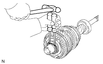
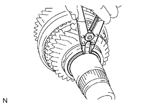
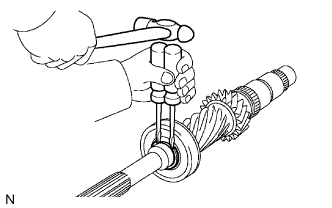
REMOVE NO. 3 TRANSMISSION CLUTCH HUB SHAFT SNAP RING
-
Using 2 screwdrivers and a hammer, tap off the snap ring.
Tech Tips
Use a piece of cloth to prevent the snap ring from flying off.
-
-
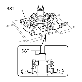
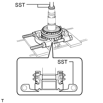
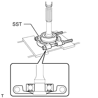
REMOVE 6TH GEAR SUB-ASSEMBLY
-
Using SST and a press, remove the No. 3 transmission clutch hub, hub sleeve, synchronizer ring and 6th gear from the input shaft.
- SST
- 09950-00020
- 09950-70010 ( 09951-07200 )
- 09950-60010 ( 09951-00300 )
Note
-
Do not tighten SST excessively.
-
Support the input shaft by hand so that it does not fall.
-
-
REMOVE 6TH GEAR NEEDLE ROLLER BEARING
-
Remove the 6th gear needle roller bearing from the input shaft.
-
-
REMOVE SPACER
-
Remove the spacer from the input shaft.
-
-
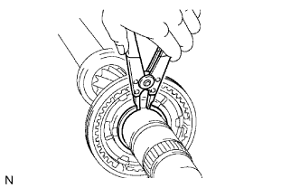
REMOVE GEAR THRUST WASHER SHAFT SNAP RING
-
Using a snap ring expander, remove the snap ring from the input shaft.
-
-
REMOVE 3RD GEAR THRUST WASHER
-
Remove the 3rd gear thrust washer from the input shaft.
-
-
REMOVE 3RD GEAR
-
Remove the 3rd gear from the input shaft.
-
-
REMOVE STRAIGHT PIN
-
Remove the straight pin from the input shaft.
-
-
REMOVE 3RD GEAR NEEDLE ROLLER BEARING
-
Remove the 3rd gear needle roller bearing from the input shaft.
-
-
REMOVE SPACER
-
Remove the spacer from the input shaft.
-
-
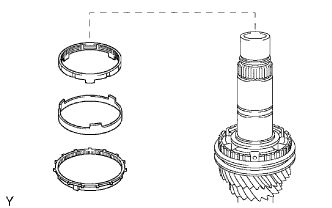
REMOVE NO. 2 SYNCHRONIZER RING SET
-
Remove the No. 2 synchronizer ring set from the input shaft.
-
-
REMOVE NO. 2 CLUTCH HUB SETTING SHAFT SNAP RING
-
Using a snap ring expander, remove the snap ring from the input shaft.
-
-
REMOVE 4TH GEAR
-
Using SST and a press, remove the No. 2 transmission clutch hub, hub sleeve, synchronizer ring and 4th gear from the input shaft.
- SST
- 09950-00020
- 09950-60010 ( 09951-00300 )
- 09950-70010 ( 09951-07200 )
Note
Support the input shaft by hand so that it does not fall.
-
-
REMOVE 4TH GEAR NEEDLE ROLLER BEARING
-
Remove the 4th gear needle roller bearing from the input shaft.
-
-
REMOVE INPUT SHAFT FRONT BEARING SNAP RING
-
Using 2 screwdrivers and a hammer, tap off the snap ring.
Tech Tips
Use a piece of cloth to prevent the snap ring from flying off.
-
-
REMOVE INPUT SHAFT FRONT BEARING
-
Using SST and a press, remove the input shaft front bearing from the input shaft.
- SST
- 09950-00020
Note
Support the input shaft by hand so that it does not fall.
-
-
REMOVE NO. 2 TRANSMISSION CLUTCH HUB
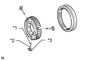
Text in Illustration *1 Spring *2 Ball *3 Synchronizer Shifting Key
-
Remove the clutch hub, 3 synchromesh shifting keys, 3 balls and 3 springs from the hub sleeve.
Tech Tips
Use a piece of cloth to prevent the balls and springs from flying off.
-
-
REMOVE NO. 3 TRANSMISSION CLUTCH HUB
Tech Tips
Perform the same procedure as for the No. 2 clutch hub.