TRANSFER SYSTEM TERMINALS OF ECU
-
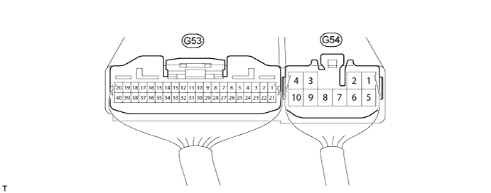
CHECK 4 WHEEL DRIVE CONTROL ECU
-
Measure the voltage and resistance according to the value(s) in the table below.
for 1GR-FE, 1KD-FTV: Terminal No. (Symbol) Wiring Color Terminal Description Condition Specified Condition G53-1 (HL1) - G54-4 (GND) GR - W-B High-low transfer shift actuator limit switch Ignition switch ON
Transfer position switch H4
10.5 to 14 V Ignition switch ON
Transfer position switch L4
Below 1.5 V G53-2 (HL2) - G54-4 (GND) LG - W-B High-low transfer shift actuator limit switch Ignition switch ON
Transfer position switch H4
Below 1.5 V Ignition switch ON
Transfer position switch L4
10.5 to 14 V G53-7 (TL2) - G54-4 (GND) V - W-B Multi mode transfer shift actuator limit switch Ignition switch ON
Center differential lock switch Lock
Below 1.5 V Ignition switch ON
Center differential lock switch Free
10.5 to 14 V G53-8 (TL3) - G54-4 (GND) G - W-B Multi mode transfer shift actuator limit switch Ignition switch ON
Center differential lock switch Lock
10.5 to 14 V Ignition switch ON
Center differential lock switch Free
Below 1.5 V G53-13 (LO) - G54-4 (GND) GR - W-B Transfer position switch Ignition switch ON
Transfer position switch H4
10.5 to 14 V Ignition switch ON
Transfer position switch L4
Below 1.5 V G53-14 (P1) - G54-4 (GND) W - W-B Multi mode transfer shift actuator
Center differential lock position detection switch
Ignition switch ON
Center differential lock switch Free
9.5 to 14 V Ignition switch ON
Center differential lock switch Lock
Below 1.5 V G53-16 (DL) - G54-4 (GND) W - W-B Center differential lock switch Ignition switch ON
Center differential lock switch ON
Below 1.5 V Ignition switch ON
Center differential lock switch OFF
9.5 to 14 V G53-17 (MTN)*1 - G54-4 (GND) B - W-B Clutch start switch Ignition switch ON
Clutch start switch ON
Below 1.5 V Ignition switch ON
Clutch start switch OFF
9.5 to 14 V G53-19 (CANH) - G54-4 (GND) G - W-B CAN communication line Ignition switch ON Pulse generation (see waveform 1) G53-20 (CANL) - G54-4 (GND) W - W-B CAN communication line Ignition switch ON Pulse generation (see waveform 2) G53-21 (L4) - G54-4 (GND) R - W-B Transfer L4 signal Ignition switch ON
Transfer position switch H4
10 to 14 V Ignition switch ON
Transfer position switch L4
Below 1.5 V G54-2 (HM1) - G54-4 (GND) B - W-B High-low transfer shift actuator motor Ignition switch ON
Transfer position switch H4 → L4 (During operation of high-low transfer shift actuator motor from HIGH to LOW)
10 to 14 V Ignition switch ON
Transfer position switch H4 → L4 (High-low transfer shift actuator motor stopped)
Below 1.5 V G54-3 (IG) - G54-4 (GND) R - W-B IG power Ignition switch ON 11 to 14 V G54-4 (GND) - Body ground W-B - Body ground Ground Always Below 1 Ω G54-6 (HM2) - G54-4 (GND) W - W-B High-low transfer shift actuator motor Ignition switch ON
Transfer position switch L4 → H4 (During operation of high-low transfer shift actuator motor from LOW to HIGH)
10 to 14 V Ignition switch ON
Transfer position switch L4 → H4 (High-low transfer shift actuator motor stopped)
Below 1.5 V G54-7 (TM2) - G54-4 (GND) V - W-B Multi mode transfer shift actuator motor Ignition switch ON
Center differential lock switch LOCK → FREE (During operation of multi mode transfer shift actuator motor from LOCK to FREE)
10 to 14 V Ignition switch ON
Center differential lock switch LOCK → FREE (Multi mode transfer shift actuator motor stopped)
Below 1.5 V G54-8 (TM1) - G54-4 (GND) P - W-B Multi mode transfer shift actuator motor Ignition switch ON
Center differential lock switch FREE → LOCK (During operation of multi mode transfer shift actuator motor from FREE to LOCK)
10 to 14 V Ignition switch ON
Center differential lock switch FREE → LOCK (Multi mode transfer shift actuator motor stopped)
Below 1.5 V *1: for Manual Transmission
for 2TR-FE, 5L-E: Terminal No. (Symbol) Wiring Color Terminal Description Condition Specified Condition G53-1 (HL1) - G54-4 (GND) GR - W-B High-low transfer shift actuator limit switch Ignition switch ON
Transfer position switch H4F or H4L
10.5 to 14 V Ignition switch ON
Transfer position switch L4L
Below 1.5 V G53-2 (HL2) - G54-4 (GND) LG - W-B High-low transfer shift actuator limit switch Ignition switch ON
Transfer position switch H4F or H4L
Below 1.5 V Ignition switch ON
Transfer position switch L4L
10.5 to 14 V G53-6 (TL1) - G54-4 (GND) W-B - W-B Transfer operating switch mode selection signal Always Below 1 Ω G53-7 (TL2) - G54-4 (GND) V - W-B Multi mode transfer shift actuator limit switch Ignition switch ON
Transfer position switch H4L or L4L
Below 1.5 V Ignition switch ON
Transfer position switch H4F
10.5 to 14 V G53-8 (TL3) - G54-4 (GND) G - W-B Multi mode transfer shift actuator limit switch Ignition switch ON
Transfer position switch H4L or L4L
10.5 to 14 V Ignition switch ON
Transfer position switch H4F
Below 1.5 V G53-11 (2-4) - G54-4 (GND) R - W-B Transfer position switch Ignition switch ON
Transfer position switch H4F or H4L
Below 1.5 V Ignition switch ON
Transfer position switch L4L
10.5 to 14 V G53-13 (LO) - G54-4 (GND) GR - W-B Transfer position switch Ignition switch ON
Transfer position switch H4F
10.5 to 14 V Ignition switch ON
Transfer position switch H4L or L4L
Below 1.5 V G53-14 (P1) - G54-4 (GND) W - W-B Multi mode transfer shift actuator
Center differential lock position detection switch
Ignition switch ON
Transfer position switch H4F
9.5 to 14 V Ignition switch ON
Transfer position switch H4L or L4L
Below 1.5 V G53-17 (MTN)*1 - G54-4 (GND) B - W-B Clutch start switch Ignition switch ON
Clutch start switch ON
Below 1.5 V Ignition switch ON
Clutch start switch OFF
9.5 to 14 V G53-19 (CANH) - G54-4 (GND) G - W-B CAN communication line Ignition switch ON Pulse generation (see waveform 1) G53-20 (CANL) - G54-4 (GND) W - W-B CAN communication line Ignition switch ON Pulse generation (see waveform 2) G53-21 (L4) - G54-4 (GND) R - W-B Transfer L4 signal Ignition switch ON
Transfer position switch H4F or H4L
10 to 14 V Ignition switch ON
Transfer position switch L4L
Below 1.5 V G54-2 (HM1) - G54-4 (GND) B - W-B High-low transfer shift actuator motor Ignition switch ON
Transfer position switch H4L → L4L (During operation of high-low transfer shift actuator motor from HIGH to LOW)
10 to 14 V Ignition switch ON
Transfer position switch H4L → L4L (High-low transfer shift actuator motor stopped)
Below 1.5 V G54-3 (IG) - G54-4 (GND) R - W-B IG power Ignition switch ON 11 to 14 V G54-4 (GND) - Body ground W-B - Body ground Ground Always Below 1 Ω G54-6 (HM2) - G54-4 (GND) W - W-B High-low transfer shift actuator motor Ignition switch ON
Transfer position switch L4L → H4L (During operation of high-low transfer shift actuator motor from LOW to HIGH)
10 to 14 V Ignition switch ON
Transfer position switch L4L → H4L (High-low transfer shift actuator motor stopped)
Below 1.5 V G54-7 (TM2) - G54-4 (GND) V - W-B Multi mode transfer shift actuator motor Ignition switch ON
Transfer position switch H4L → H4F (During operation of multi mode transfer shift actuator motor from LOCK to FREE)
10 to 14 V Ignition switch ON
Transfer position switch H4L → H4F (Multi mode transfer shift actuator motor stopped)
Below 1.5 V G54-8 (TM1) - G54-4 (GND) P - W-B Multi mode transfer shift actuator motor Ignition switch ON
Transfer position switch H4F → H4L (During operation of multi mode transfer shift actuator motor from FREE to LOCK)
10 to 14 V Ignition switch ON
Transfer position switch H4F → H4L (Multi mode transfer shift actuator motor stopped)
Below 1.5 V *1: for Manual Transmission
-
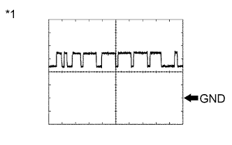
Text in Illustration *1 Waveform 1 Using an oscilloscope, check waveform 1.
Waveform 1 (Reference) Item Content Terminal No. (Symbol) G53-19 (CANH) - G54-4 (GND) Tool setting 1 V/DIV., 10 μsec./DIV. Condition Engine stopped and ignition switch ON Tech Tips
The waveform varies depending on the CAN communication signal.
-
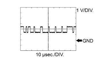
Text in Illustration *1 Waveform 2 Using an oscilloscope, check waveform 2.
Waveform 2 (Reference) Item Content Terminal No. (Symbol) G53-20 (CANL) - G54-4 (GND) Tool setting 1 V/DIV., 10 μsec./DIV. Condition Engine stopped and ignition switch ON Tech Tips
The waveform varies depending on the CAN communication signal.
-