MANUAL TRANSMISSION UNIT REASSEMBLY

-
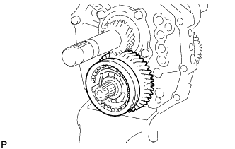
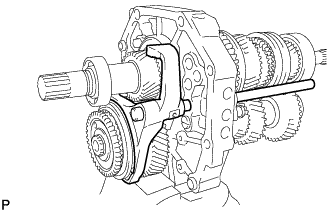
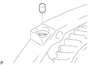
INSTALL OUTPUT SHAFT
-
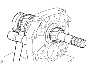
Apply gear oil to the sliding part of the output shaft.
-
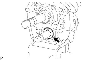
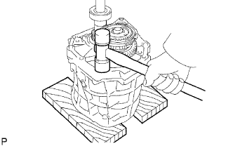
Using a plastic-faced hammer, install the output shaft by tapping the intermediate plate.
-
-
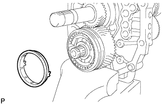
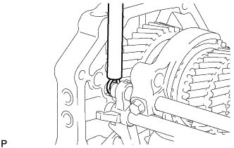
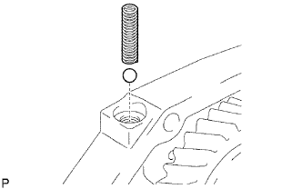
INSTALL OUTPUT SHAFT BEARING SHAFT SNAP RING (for Center Bearing Side)
-
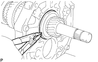
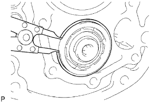
Using a snap ring expander, install the output shaft bearing shaft snap ring to the output shaft center bearing.
-
-
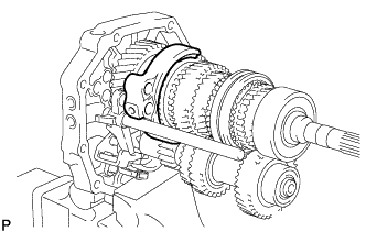
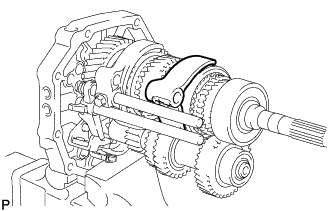
INSTALL INPUT SHAFT
-
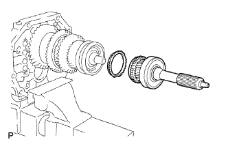
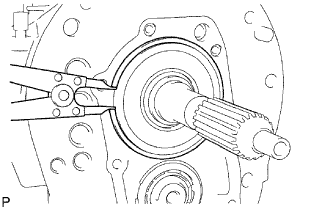
Apply gear oil to the input shaft and No. 2 synchronizer ring, and install them to the output shaft.
Note
-
Install the No. 2 synchronizer ring so that its groove fits onto the No. 2 synchromesh shifting key.
-
Check that the input shaft rotates smoothly.
-
-
-
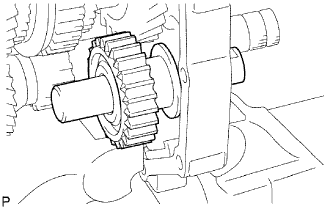
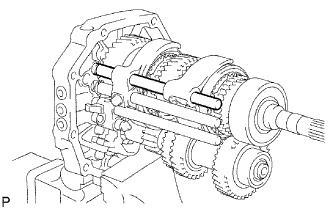
INSTALL COUNTER GEAR
-
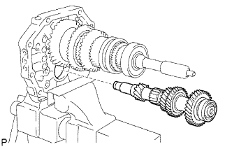
Install the counter gear to the intermediate plate.
-
-
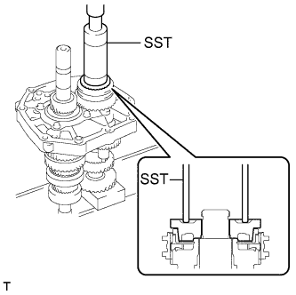
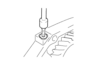
INSTALL COUNTER SHAFT CENTER BEARING
-
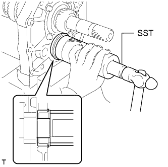
Using SST and a hammer, tap in a new counter shaft center bearing to the intermediate plate.
- SST
- 09316-60011
Tech Tips
Install the counter shaft center bearing while tapping the tip of the counter gear with a plastic-faced hammer so that the counter gear does not hit the side wall of the output shaft gear by being pushed forward.
-
Using a snap ring expander, install the snap ring to the counter shaft center bearing.
-
-
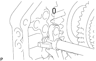
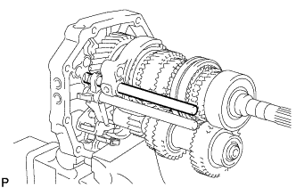
INSTALL REVERSE IDLER GEAR SUB-ASSEMBLY
-
Apply gear oil to the sliding parts of the reverse idler gear sub-assembly and reverse idler gear shaft, and install the reverse idler gear sub-assembly and reverse idler shaft to the intermediate plate.
Note
Be sure to install the reverse idler gear shaft from the rear with the groove facing the rear side.
-
-
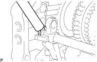
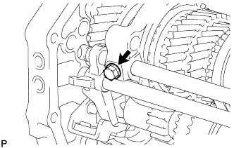
INSTALL OUTPUT SHAFT REAR BEARING RETAINER
-
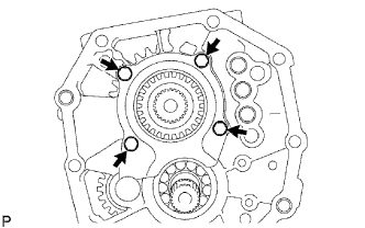
Insert the protrusion of the output shaft rear bearing retainer into the groove of the reverse idler gear shaft. Then install the output shaft rear bearing retainer with the 4 bolts.
- Torque:
- 25 N*m { 255 kgf*cm, 18 ft.*lbf }
-
-
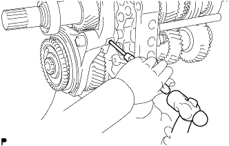
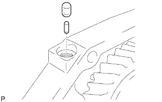
INSTALL 5TH GEAR THRUST WASHER PIN
-
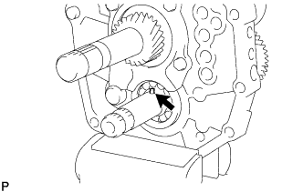
Apply MP grease to the 5th gear thrust washer pin and install it to the counter gear.
-
-
INSTALL 5TH GEAR THRUST WASHER
-
Apply gear oil to the 5th gear thrust washer and install it to the counter gear.
Note
Install the 5th gear thrust washer so that its chamfered side faces the front side.
-
-
INSTALL NO. 3 SYNCHROMESH SHIFTING KEY
-
Apply gear oil to the sliding part of No. 3 transmission hub sleeve and install it to the counter 5th gear.
Note
Make sure that the No. 3 transmission hub sleeve and counter 5th gear are facing the proper direction.
-
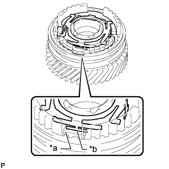
Text in Illustration *a Cutout *b Protrusion Install the 2 No. 3 synchromesh shifting keys and No. 3 synchromesh shifting key spring to the counter 5th gear as shown in the illustration.
Tech Tips
When installing the No. 3 synchromesh shifting key spring, make sure the protrusion fits into the cutout.
-
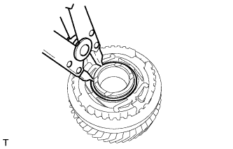
Using a snap ring expander, install the snap ring to the counter 5th gear.
-
-
INSTALL COUNTER 5TH GEAR BEARING
-
Apply gear oil to the counter 5th gear bearing and install it to the counter 5th gear.
-
-
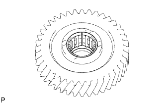
INSTALL COUNTER 5TH GEAR
-
Apply gear oil to the counter 5th gear and No. 3 transmission hub sleeve, and install the counter 5th gear to the counter gear.
-
-
INSTALL OUTER NO. 3 SYNCHRONIZER RING
-
Apply gear oil to the outer No. 3 synchronizer ring and install it to the counter gear.
Note
Install the outer No. 3 synchronizer ring so that its groove fits onto the No. 3 synchromesh shifting key.
-
-
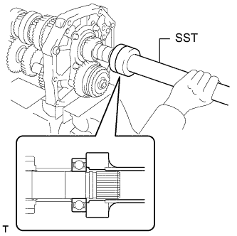
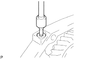
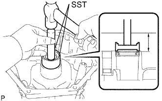
INSTALL NO. 5 GEAR SPLINE PIECE
-
Using SST and a press, press in the No. 5 gear spline piece to the counter gear.
- SST
- 09316-60011 ( 09316-00011 )
Note
Check that the counter 5th gear rotates freely.
-
-
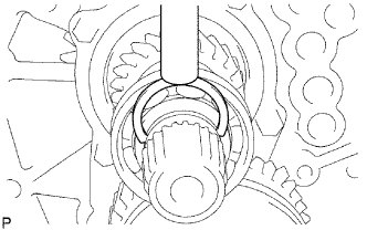
INSTALL COUNTER GEAR REAR SHAFT SNAP RING
-
Select a counter gear rear shaft snap ring so that the thrust clearance between the No. 5 gear spline piece and counter gear rear shaft snap ring to be within the specification.
Standard clearance 0.10 mm (0.00394 in.) or less Snap Ring Thickness Thickness 2.85 mm (0.1122 in.) 2.90 mm (0.1141 in.) 2.95 mm (0.1161 in.) 3.00 mm (0.1181 in.) 3.05 mm (0.1200 in.) 3.10 mm (0.1220 in.) 3.15 mm (0.1240 in.) -
Secure the intermediate plate in a vise between aluminum plates.
-
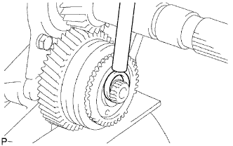
Using a brass bar and hammer, tap on the counter gear rear shaft snap ring.
-
-
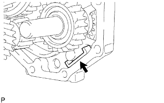
INSPECT COUNTER 5TH GEAR THRUST CLEARANCE
-
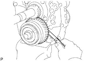
Using a feeler gauge, measure the thrust clearance.
Standard clearance 0.10 to 0.35 mm (0.00394 to 0.0137 in.)
-
If the clearance is not as specified, replace the counter 5th gear.
-
-
-
INSPECT COUNTER 5TH GEAR RADIAL CLEARANCE
-
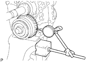
Using a dial indicator, measure the radial clearance.
Standard clearance 0.015 to 0.068 mm (0.000591 to 0.00267 in.)
-
If the clearance is not as specified, replace the counter 5th gear bearing with a new one.
-
-
-
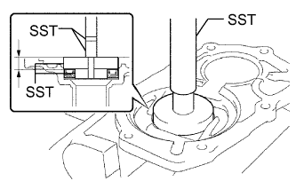
INSTALL OUTPUT SHAFT REAR BEARING
-
Using SST and a hammer, press in the output shaft spacer and a new output shaft rear bearing to the output shaft.
- SST
- 09309-35010
-
-
INSTALL OUTPUT SHAFT BEARING SHAFT SNAP RING (for Rear Bearing Side)
-
Select a output shaft bearing shaft snap ring so that the thrust clearance between the output shaft bearing shaft and output shaft bearing shaft snap ring to be within the specification.
Standard clearance 0.10 mm (0.00394 in.) or less Snap Ring Thickness Thickness Thickness 2.65 mm (0.1043 in.) 3.10 mm (0.1220 in.) 2.70 mm (0.1063 in.) 3.15 mm (0.1240 in.) 2.75 mm (0.1083 in.) 3.20 mm (0.1260 in.) 2.80 mm (0.1102 in.) 3.25 mm (0.1280 in.) 2.85 mm (0.1122 in.) 3.30 mm (0.1299 in.) 2.90 mm (0.1142 in.) 3.35 mm (0.1319 in.) 2.95 mm (0.1161 in.) 3.40 mm (0.1339 in.) 3.00 mm (0.1181 in.) 3.45 mm (0.1358 in.) 3.05 mm (0.1200 in.) - -
Using a brass bar and hammer, tap on the output shaft bearing shaft snap ring.
-
-
INSTALL REVERSE SHIFT ARM BRACKET
-
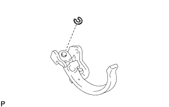
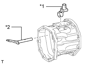
Install the reverse shift arm to the reverse shift arm bracket with a new snap ring.
-
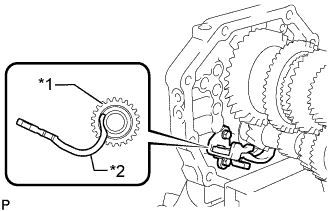
Text in Illustration *1 Reverse Idler Gear Sub-assembly *2 Reverse Shift Arm Insert the tip of the reverse shift arm into the reverse idler gear sub-assembly.
-
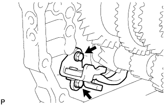
Install the reverse shift arm bracket with the 2 bolts.
- Torque:
- 18 N*m { 184 kgf*cm, 13 ft.*lbf }
-
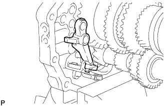
Install the torsion spring to the reverse shift arm bracket.
Note
Make sure that the torsion spring is securely installed to the reverse shift arm.
-
-
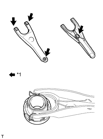
INSTALL REVERSE SHIFT FORK
-
Install the reverse shift fork to the reverse shift arm.
-
-
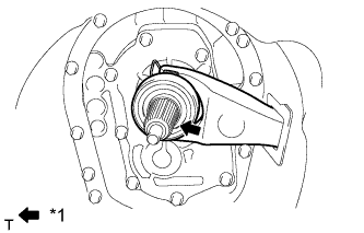
INSTALL NO. 3 GEAR SHIFT FORK SHAFT
-
Install the No. 3 shift fork to the No. 3 transmission hub sleeve and the No. 3 gear shift fork shaft to the intermediate plate from the front side.
-
Install the straight pin to the reverse shift fork.
-
Using a brass bar and hammer, tap on the snap ring to the No. 3 gear shift fork shaft.
-
Using a 5 mm pin punch and hammer, tap on the shift fork set slotted spring pin to the No. 3 shift fork.
-
-
INSTALL NO. 1 GEAR SHIFT FORK SHAFT
-
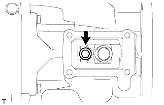
Install the No. 1 shift interlock roller to the intermediate plate.
-
Install the No. 1 shift fork to the reverse gear.
-
Install the No. 1 gear shift fork shaft to the intermediate plate from the rear side.
-
Install a new bolt to the No. 1 shift fork.
- Torque:
- 20 N*m { 199 kgf*cm, 14 ft.*lbf }
-
Using a brass bar and hammer, tap in the snap ring to the No. 1 gear shift fork shaft.
-
-
INSTALL NO. 2 GEAR SHIFT FORK SHAFT
-
Install the shift interlock pin and No. 1 shift interlock roller to the intermediate plate.
-
Install the No. 2 shift fork to the No. 2 transmission hub sleeve.
-
Apply gear oil to the No. 2 gear shift fork shaft and install it to the intermediate plate from the rear side.
-
Install a new bolt to the No. 2 shift fork.
- Torque:
- 20 N*m { 199 kgf*cm, 14 ft.*lbf }
-
Using a brass bar and hammer, tap on the snap ring to the No. 2 gear shift fork shaft.
-
-
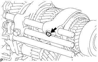
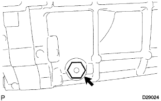
INSTALL NO. 1 SHIFT DETENT BALL SPRING SEAT
-
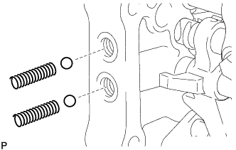
Install the 2 detent balls and 2 compression springs to the intermediate plate.
-
for Type A:
Apply adhesive to 2 or 3 threads of the 2 No. 1 shift detent ball spring seats.
Adhesive Toyota Genuine Adhesive 1344, Three Bond 1344 or equivalent -

for Type A:
Using a 6 mm hexagon socket wrench, install the 2 No. 1 shift detent ball spring seats to the intermediate plate.
- Torque:
- 19 N*m { 189 kgf*cm, 14 ft.*lbf }
-
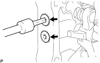
for Type B:
Using a T40 "TORX" socket wrench, install the 2 No. 1 shift detent ball spring seats to the intermediate plate.
- Torque:
- 19 N*m { 189 kgf*cm, 14 ft.*lbf }
-
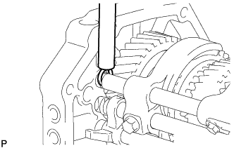
Install the detent ball and low side compression spring to the intermediate plate.
-
for Type A:
Apply adhesive to 2 or 3 threads of the No. 1 shift detent ball spring seat.
Adhesive Toyota Genuine Adhesive 1344, Three Bond 1344 or equivalent -
for Type A:
Using a 6 mm hexagon socket wrench, install the No. 1 shift detent ball spring seat to the intermediate plate.
-
for Type B:
Using a T40 "TORX" socket wrench, install the No. 1 shift detent ball spring seat to the intermediate plate.
- Torque:
- 19 N*m { 189 kgf*cm, 14 ft.*lbf }
-
-
INSTALL TRANSMISSION MAGNET
-
Clean the transmission magnet and install it to the intermediate plate.
-
-
INSTALL MANUAL TRANSMISSION CASE
-
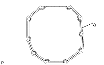
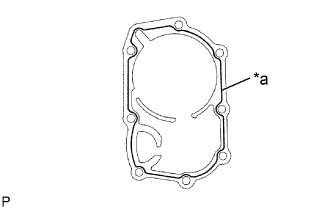
Text in Illustration *a Seal Packing Apply seal packing to the manual transmission case as shown in the illustration.
Seal packing Toyota Genuine Seal Packing 1281, Three Bond 1281 or equivalent Seal diameter 1.2 mm (0.0472 in.) Note
Assemble parts within 10 minutes of application. Otherwise, the packing (FIPG) material must be removed and reapplied.
-
Place the manual transmission case on wooden blocks.
-
Using a plastic-faced hammer, tap the intermediate plate to install the manual transmission case.
-
-
INSTALL NO. 1 COUNTER GEAR FRONT BEARING SNAP RING
-
Using a snap ring expander, install the No. 1 counter gear front bearing snap ring to the counter gear front bearing.
-
-
INSTALL FRONT BEARING SHAFT SNAP RING
-
Using a snap ring expander, install the front bearing shaft snap ring to the input shaft front bearing.
-
-
INSTALL TRANSMISSION FRONT BEARING RETAINER OIL SEAL
-
Using SST and a hammer, tap in a new transmission front bearing retainer oil seal to the front bearing retainer.
- SST
- 09950-60010 ( 09951-00300, 09951-00520, 09952-06010 )
- 09950-70010 ( 09951-07100 )
Standard oil seal depth 11.20 to 12.20 mm (0.441 to 0.480 in.) -
Apply a light coat of MP grease to the lip of the transmission front bearing retainer oil seal.
-
-
INSTALL FRONT BEARING RETAINER
-
Text in Illustration *a Seal Packing Apply seal packing to the front bearing retainer as shown in the illustration.
Seal packing Toyota Genuine Seal Packing 1281, Three Bond 1281 or equivalent Seal diameter 1.2 mm (0.0472 in.) Note
Assemble parts within 10 minutes of application. Otherwise, the packing (FIPG) material must be removed and reapplied.
-
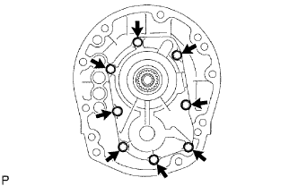
Install the front bearing retainer to the manual transmission case with the 8 bolts.
- Torque:
- 17 N*m { 168 kgf*cm, 12 ft.*lbf }
-
Check that the input shaft and output shaft rotate smoothly.
-
-
INSTALL TRANSFER ADAPTER OIL SEAL
-
Using SST and a hammer, tap in a new transfer adapter oil seal to the transfer adapter.
- SST
- 09710-30050
- 09950-70010 ( 09951-07100 )
Standard oil seal depth 45.4 to 46.4 mm (1.79 to 1.82 in.) -
Apply a light coat of MP grease to the lip of the transfer adapter oil seal.
-
-
INSTALL REVERSE RESTRICT PIN ASSEMBLY
-
Install the reverse restrict pin assembly to the transfer adapter.
-
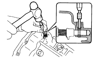
Using a 5 mm pin punch and hammer, tap in the reverse restrict pin slotted spring pin to the transfer adapter.
-
Using a T40 "TORX" socket wrench, install the reverse restrict pin plug to the transfer adapter.
- Torque:
- 19 N*m { 189 kgf*cm, 14 ft.*lbf }
-
-
INSTALL TRANSFER OIL RECEIVER PIPE
-
Install the transfer oil receiver pipe to the transfer adapter.
-
-
INSTALL TRANSFER ADAPTER
-
Text in Illustration *a Seal Packing Apply seal packing to the transfer adapter as shown in the illustration.
Seal packing Toyota Genuine Seal Packing 1281, Three Bond 1281 or equivalent Seal diameter 1.2 mm (0.0472 in.) Note
Assemble parts within 10 minutes of application. Otherwise, the packing (FIPG) material must be removed and reapplied.
-
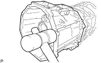
Using a plastic-faced hammer, tap the transfer adapter to attach it to the manual transmission case.
-
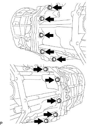
Install the transfer adapter to the manual transmission case with the 10 bolts.
- Torque:
- 37 N*m { 377 kgf*cm, 27 ft.*lbf }
-
-
INSTALL SHIFT AND SELECT LEVER
-
Text in Illustration *1 Shift Lever Housing *2 Shift and Select Lever Install the shift and select lever with the shift lever housing to the transfer adapter.
-
Install the bolt to the shift lever housing.
- Torque:
- 33 N*m { 340 kgf*cm, 25 ft.*lbf }
-
-
INSTALL FLOOR SHIFT CONTROL SHIFT LEVER RETAINER SUB-ASSEMBLY
-
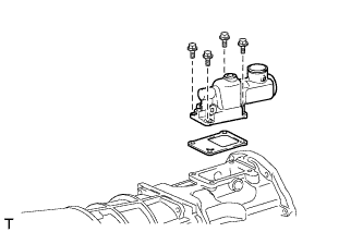
Install the floor shift control shift lever retainer sub-assembly and a new gasket with the 4 bolts.
- Torque:
- 18 N*m { 184 kgf*cm, 13 ft.*lbf }
-
-
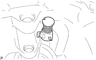
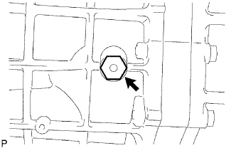
INSTALL RESTRICT PIN
-
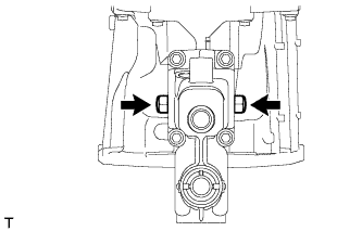
Install the 2 restrict pins.
- Torque:
- 37 N*m { 377 kgf*cm, 27 ft.*lbf }
-
-
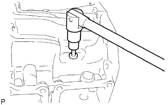
INSTALL BACK-UP LIGHT SWITCH ASSEMBLY
-
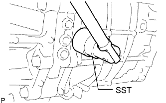
Using SST, install a new gasket and the back-up light switch assembly to the manual transmission case.
- SST
- 09817-16011
- Torque:
- 44 N*m { 449 kgf*cm, 32 ft.*lbf }
-
-
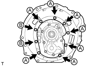
INSTALL CLUTCH HOUSING
-
Temporarily install the clutch housing with the 7 bolts labeled A.
-
Apply adhesive to the 2 bolts labeled B.
Adhesive Toyota Genuine Adhesive 1344, Three Bond 1344 or equivalent -
Temporarily install the 2 bolts labeled B.
-
Tighten the 9 bolts.
- Torque:
- 36 N*m { 367 kgf*cm, 27 ft.*lbf }
-
-
INSTALL RELEASE FORK SUPPORT
-
Install the release fork support to the manual transmission unit.
- Torque:
- 47 N*m { 479 kgf*cm, 34 ft.*lbf }
-
-
INSTALL CLUTCH RELEASE BEARING ASSEMBLY
Text in Illustration *1 Release hub grease
-
Apply release hub grease to the clutch release bearing, and then install it to the clutch release fork with the clip.
Grease Toyota Genuine Release Hub Grease or equivalent
-
-
INSTALL CLUTCH RELEASE FORK SUB-ASSEMBLY
-
Install the clutch release fork.
Note
After the installation, move the fork forward and backward to check that the release bearing slides smoothly.
-
Text in Illustration *1 Clutch spline grease Apply clutch spline grease to the spline of the input shaft.
Grease Toyota Genuine Clutch Spline Grease or equivalent
-
-
INSTALL CLUTCH RELEASE FORK BOOT
-
Install the release fork boot to the clutch housing.
-
-
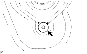
INSTALL DRAIN PLUG
-
Install a new gasket and the drain plug to the manual transmission case.
- Torque:
- 37 N*m { 377 kgf*cm, 27 ft.*lbf }
-
-
INSTALL MANUAL TRANSMISSION FILLER PLUG
-
Install a new gasket and the manual transmission filler plug to the manual transmission case.
- Torque:
- 37 N*m { 377 kgf*cm, 27 ft.*lbf }
-