MANUAL TRANSMISSION UNIT DISASSEMBLY

-
REMOVE MANUAL TRANSMISSION FILLER PLUG
-
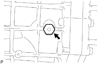
Remove the manual transmission filler plug and gasket from the manual transmission case.
-
-
REMOVE DRAIN PLUG
-
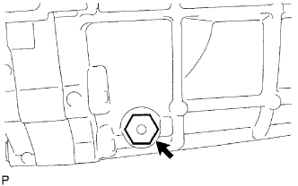
Remove the drain plug and gasket from the manual transmission case.
-
-
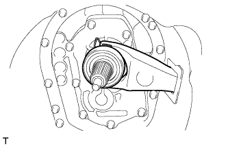
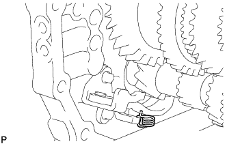
REMOVE CLUTCH RELEASE FORK SUB-ASSEMBLY
-
Remove the release fork and release bearing from the clutch housing.
-
-
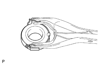
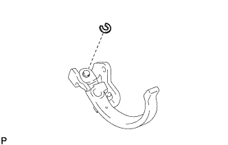
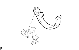
REMOVE CLUTCH RELEASE BEARING ASSEMBLY
-
Remove the clip and release bearing from the release fork.
-
-
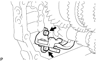
REMOVE RELEASE FORK SUPPORT
-
Remove the release fork support from the clutch housing.
-
-
REMOVE CLUTCH RELEASE FORK BOOT
-
Remove the clutch release fork boot from the clutch housing.
-
-
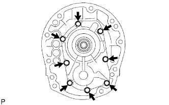
REMOVE CLUTCH HOUSING
-
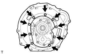
Remove the 9 bolts.
-
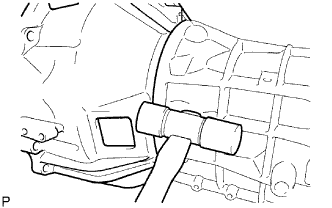
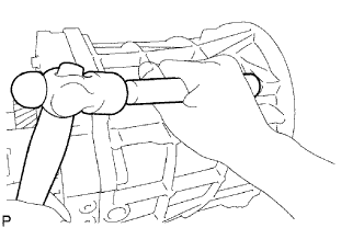
Using a plastic-faced hammer, tap off the clutch housing from the manual transmission case.
-
-
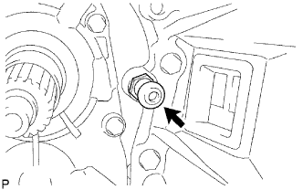
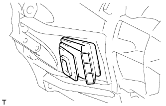
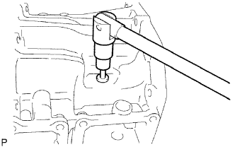
REMOVE BACK-UP LIGHT SWITCH ASSEMBLY
-
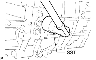
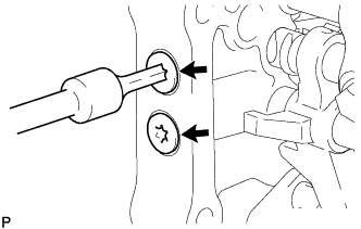
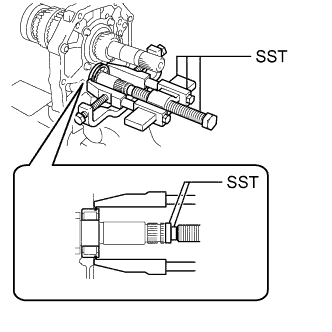
Using SST, remove the back-up light switch assembly and gasket from the manual transmission case.
- SST
- 09817-16011
-
-
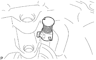
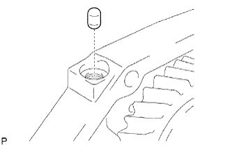
REMOVE RESTRICT PIN
-
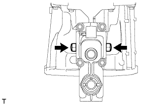
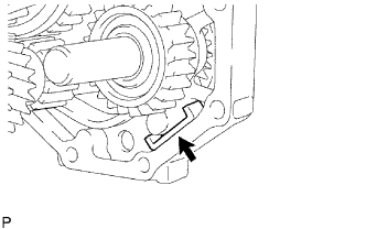
Remove the 2 restrict pins from the transfer adapter.
-
-
REMOVE FLOOR SHIFT CONTROL SHIFT LEVER RETAINER SUB-ASSEMBLY
-
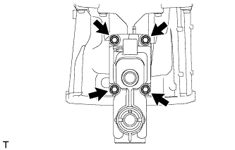
Remove the 4 bolts and floor shift control shift lever retainer sub-assembly.
-
Remove the gasket.
-
-
REMOVE TRANSFER ADAPTER
-
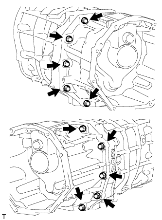
Remove the 10 bolts.
-
Using a brass bar and hammer, tap off the transfer adapter from the manual transmission case.
-
-
REMOVE TRANSFER OIL RECEIVER PIPE
-
Remove the transfer oil receiver pipe from the transfer adapter.
-
-
REMOVE SHIFT AND SELECT LEVER
-
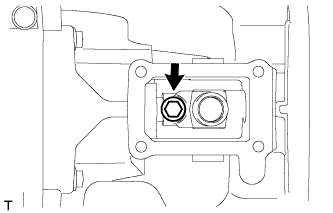
Remove the bolt from the shift lever housing.
-
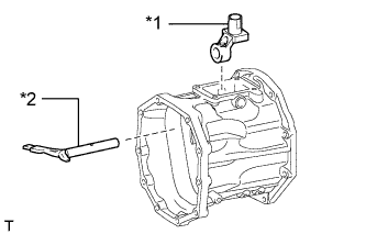
Text in Illustration *1 Shift Lever Housing *2 Shift and Select Lever Remove the shift and select lever and shift lever housing from the transfer adapter.
-
-
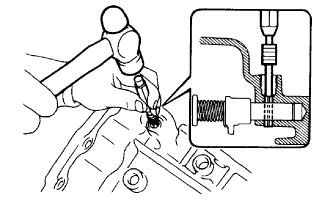
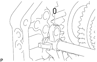
REMOVE REVERSE RESTRICT PIN ASSEMBLY
-
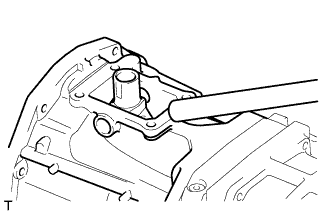
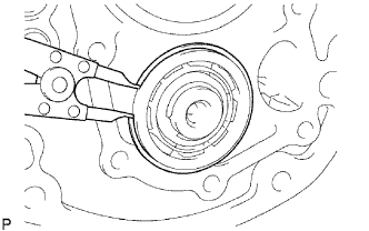
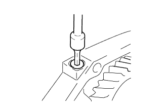
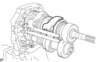
Using a T40 "TORX" socket wrench, remove the reverse restrict pin plug.
-
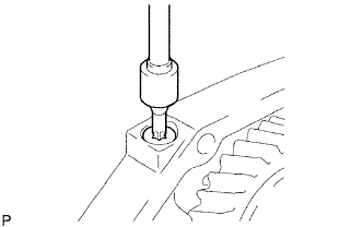
Using a 5 mm pin punch and hammer, tap out the reverse restrict pin slotted spring pin.
-
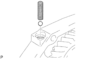
Remove the reverse restrict pin assembly.
-
-
REMOVE TRANSFER ADAPTER OIL SEAL
-
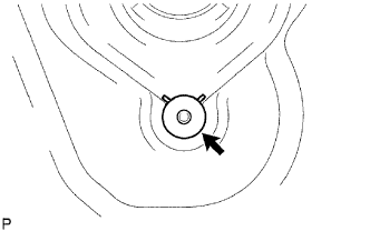
Using a screwdriver and hammer, tap out the transfer adapter oil seal from the transfer adapter.
-
-
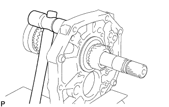
REMOVE FRONT BEARING RETAINER
-
Remove the 8 bolts.
-
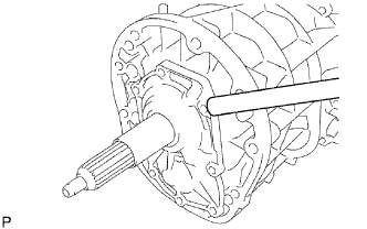
Using a brass bar and hammer, tap off the front bearing retainer from the manual transmission case.
-
-
REMOVE TRANSMISSION FRONT BEARING RETAINER OIL SEAL
-
Secure the front bearing retainer in a vise between aluminum plates.
-
Using SST, tap out the transmission front bearing retainer oil seal.
- SST
- 09308-00010
-
-
REMOVE FRONT BEARING SHAFT SNAP RING
-
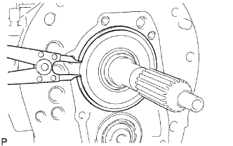
Using a snap ring expander, remove the front bearing shaft snap ring from the input shaft front bearing.
-
-
REMOVE FRONT NO. 1 COUNTER GEAR BEARING SNAP RING
-
Using a snap ring expander, remove the front No. 1 counter bearing snap ring from the front counter gear bearing.
-
-
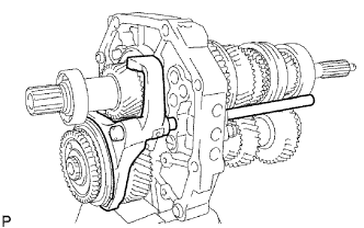
REMOVE MANUAL TRANSMISSION CASE
-
Using a brass bar and hammer, tap off the manual transmission case from the intermediate plate.
-
-
REMOVE TRANSMISSION MAGNET
-
Remove the transmission magnet from the intermediate plate.
-
-
FIX INTERMEDIATE PLATE
-
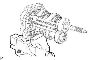
Secure the intermediate plate in a vise between aluminum plates.
-
-
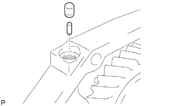
REMOVE NO. 1 SHIFT DETENT BALL SPRING SEAT
-
for Type A:
Using a 6 mm hexagon socket wrench, remove the No. 1 shift detent ball spring seat from the intermediate plate.
-
for Type B:
Using a T40 "TORX" socket wrench, remove the No. 1 shift detent ball spring seat from the intermediate plate.
-
Using a magnet hand, remove the compression spring and detent ball from the intermediate plate.
-

for Type A:
Using a 6 mm hexagon socket wrench, remove the 2 No. 1 shift detent ball spring seats from the intermediate plate.
-
for Type B:
Using a T40 "TORX" socket wrench, remove the 2 No. 1 shift detent ball spring seats from the intermediate plate.
-
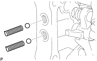
Using a magnet hand, remove the 2 compression springs and 2 detent balls from the intermediate plate.
-
-
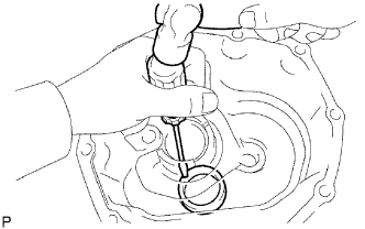
REMOVE NO. 2 GEAR SHIFT FORK SHAFT
-
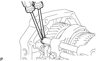
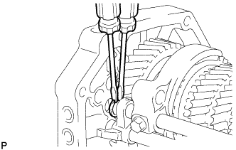
Using 2 screwdrivers and a hammer, tap off the snap ring from the No. 2 gear shift fork shaft.
Note
Use a piece of cloth to prevent the snap ring from flying off.
-
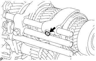
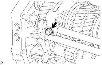
Remove the bolt from the No. 2 shift fork.
-
Remove the No. 2 gear shift fork shaft from the intermediate plate.
-
Remove the No. 2 shift fork from the No. 2 transmission hub sleeve.
-
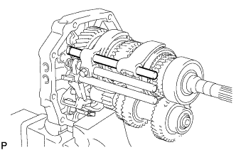
Using a magnet hand, remove the No. 1 shift interlock roller and shift interlock pin from the intermediate plate.
-
-
REMOVE NO. 1 GEAR SHIFT FORK SHAFT
-
Using 2 screwdrivers and a hammer, tap off the snap ring from the No. 1 gear shift fork shaft.
Note
Use a piece of cloth to prevent the snap ring from flying off.
-
Remove the bolt from the No. 1 shift fork.
-
Remove the No. 1 gear shift fork shaft from the intermediate plate.
-
Remove the No. 1 shift fork from the reverse gear.
-
-
REMOVE NO. 3 GEAR SHIFT FORK SHAFT
-
Using a 5 mm pin punch and hammer, tap out the shift fork set slotted spring pin from the No. 3 shift fork.
-
Using 2 screwdrivers and a hammer, tap off the snap ring from the No. 3 gear shift fork shaft.
Note
Use a piece of cloth to prevent the snap ring from flying off.
-
Using a magnet hand, remove the straight pin from the reverse shift fork.
-
Remove the No. 3 shift fork and No. 3 gear shift fork shaft from the intermediate plate.
-
Using a magnet hand, remove the No. 1 shift interlock roller from the intermediate plate.
-
-
REMOVE REVERSE SHIFT FORK
-
Remove the reverse shift fork from the reverse shift arm.
-
-
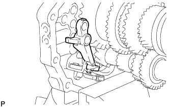
REMOVE REVERSE SHIFT ARM BRACKET
-
Remove the torsion spring from the reverse shift arm bracket.
-
Remove the 2 bolts and reverse shift arm bracket from the intermediate plate.
-
Using a screwdriver, pry out the snap ring from the reverse shift arm bracket.
-
Remove the reverse shift arm from the reverse shift arm bracket.
-
-
REMOVE OUTPUT SHAFT BEARING SHAFT SNAP RING (for Rear Bearing Side)
-
Using 2 screwdrivers and a hammer, tap off the output shaft bearing shaft snap ring from the output shaft rear bearing.
Note
Use a piece of cloth to prevent the snap ring from flying off.
-
-
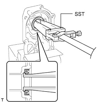
REMOVE OUTPUT SHAFT REAR BEARING
-
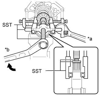
Text in Illustration *a Hold *b Turn Using SST, remove the output shaft rear bearing and output shaft spacer from the output shaft.
- SST
- 09950-40011 ( 09951-04010, 09952-04010, 09953-04020, 09954-04010, 09955-04051, 09957-04010, 09958-04011 )
- 09950-60010 ( 09951-00300 )
-
-
INSPECT COUNTER 5TH GEAR THRUST CLEARANCE
-
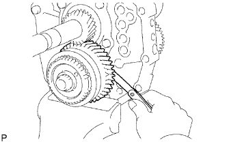
Using a feeler gauge, measure the thrust clearance.
Standard clearance 0.10 to 0.35 mm (0.00394 to 0.0137 in.)
-
If the clearance is not as specified, replace the counter 5th gear.
-
-
-
INSPECT COUNTER 5TH GEAR RADIAL CLEARANCE
-
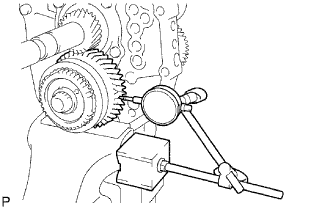
Using a dial indicator, measure the radial clearance.
Standard clearance 0.015 to 0.068 mm (0.000591 to 0.00267 in.)
-
If the clearance is not as specified, replace the counter 5th gear bearing with a new one.
-
-
-
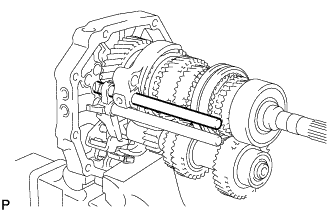
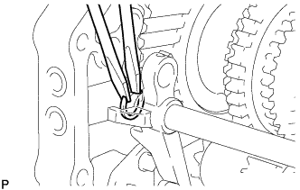
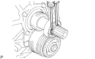
REMOVE COUNTER GEAR REAR SHAFT SNAP RING
-
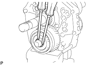
Using 2 screwdrivers and a hammer, tap off the counter gear rear shaft snap ring from the counter gear.
Note
Use a piece of cloth to prevent the counter gear rear shaft snap ring from flying off.
-
-
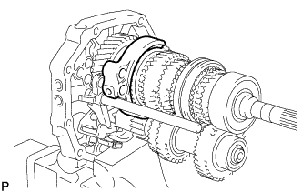
REMOVE NO. 3 TRANSMISSION HUB SLEEVE
-
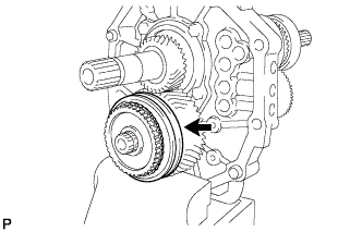
Remove the No. 3 transmission hub sleeve from the counter 5th gear.
-
-
REMOVE NO. 5 GEAR SPLINE PIECE
-
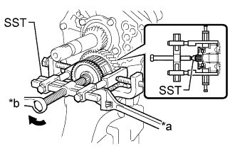
Text in Illustration *a Hold *b Turn Using SST, remove the counter 5th gear together with the counter 5th gear bearing, 2 No. 3 synchromesh shifting keys, No. 3 synchromesh shifting key spring, No. 3 synchronizer ring and No. 5 gear spline piece from the counter 5th gear.
- SST
- 09950-50013 ( 09951-05010, 09952-05010, 09953-05020, 09954-05021, 09957-04010 )
-
-
REMOVE NO. 5 GEAR SPLINE PIECE
-
Remove the No. 5 gear spline piece from the counter 5th gear.
-
-
REMOVE OUTER NO. 3 SYNCHRONIZER RING
-
Remove the outer No. 3 synchronizer ring from the counter 5th gear.
-
-
REMOVE COUNTER 5TH GEAR BEARING
-
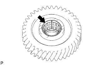
Remove the counter 5th gear bearing from the counter 5th gear.
-
-
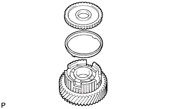
REMOVE NO. 3 SYNCHROMESH SHIFTING KEY
-
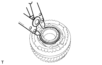
Using a snap ring expander, remove the shaft snap ring.
-
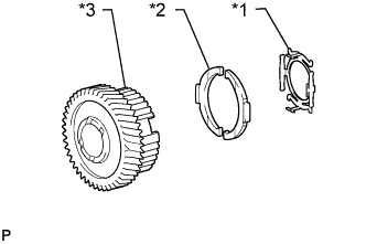
Text in Illustration *1 No. 3 Synchromesh Shifting Key Spring *2 No. 3 Synchromesh Shifting Key *3 Counter 5th Gear Remove the No. 3 synchromesh shifting keys and No. 3 synchromesh shifting key spring from the counter 5th gear.
-
-
REMOVE 5TH GEAR THRUST WASHER
-
Remove the 5th gear thrust washer from the counter gear.
-
-
REMOVE 5TH GEAR THRUST WASHER PIN
-
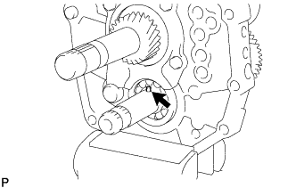
Remove the 5th gear thrust washer pin from the counter gear.
-
-
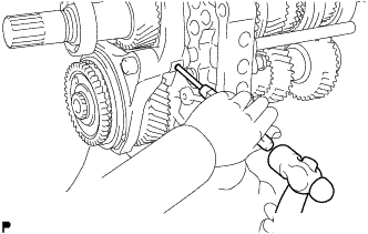
REMOVE OUTPUT SHAFT REAR BEARING RETAINER
-
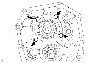
Remove the 4 bolts and output shaft rear bearing retainer from the intermediate plate.
-
-
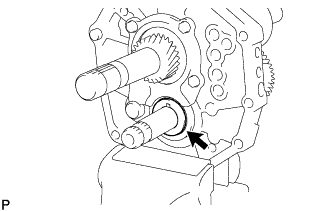
REMOVE REVERSE IDLER GEAR SUB-ASSEMBLY
-
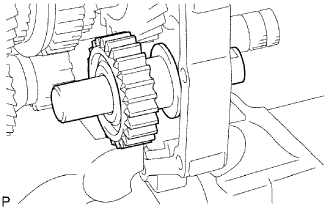
Pull out the reverse idler gear shaft from the rear side and remove the reverse idler gear sub-assembly from the intermediate plate.
-
-
REMOVE COUNTER SHAFT CENTER BEARING
-
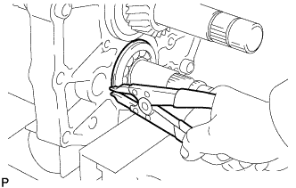
Using a snap ring expander, remove the snap ring from the counter shaft center bearing.
-
Using SST, remove the counter shaft center bearing from the intermediate plate.
- SST
- 09950-40011 ( 09951-04010, 09952-04010, 09953-04020, 09954-04010, 09955-04011, 09957-04010, 09958-04011 )
- 09950-60010 ( 09951-00260 )
Note
Do not drop the counter gear. Hold the front side of the counter gear when removing the bearing outer race.
-
-
REMOVE COUNTER GEAR
-
Remove the counter gear from the intermediate plate.
-
-
REMOVE INPUT SHAFT
-
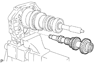
Remove the input shaft and No. 2 synchronizer ring from the output shaft.
Note
Do not drop the input shaft bearing or No. 2 synchronizer ring.
-
-
REMOVE OUTPUT SHAFT BEARING SHAFT SNAP RING (for Center Bearing Side)
-
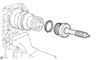
Using a snap ring expander, remove the output shaft bearing shaft snap ring from the output shaft center bearing.
-
-
REMOVE OUTPUT SHAFT
-
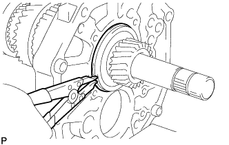
Using a plastic-faced hammer, remove the output shaft by tapping the intermediate plate.
-