CLUTCH MASTER CYLINDER (for LHD) INSTALLATION

-
INSTALL CLUTCH MASTER CYLINDER ASSEMBLY
-
Install the clutch master cylinder with the 2 bolts.
- Torque:
- 12 N*m { 120 kgf*cm, 9 ft.*lbf }
-
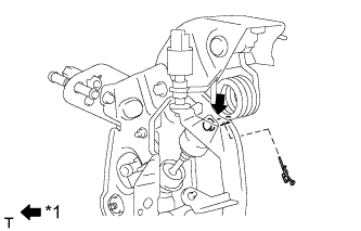
Text in Illustration *1 MP grease Apply MP grease to the contact surfaces of the pin and clevis bush.
-
Connect the clevis to the clutch pedal with the pin.
-
Install a new clip to the pin.
-
Install the clutch start switch with the nut.
- Torque:
- 16 N*m { 160 kgf*cm, 12 ft.*lbf }
-
Using a union nut wrench, connect the flexible tube.
- Torque:
- 15 N*m { 155 kgf*cm, 11 ft.*lbf }
Note
Use the formula to calculate special torque values for situations where a union nut wrench is combined with a torque wrench Click here.
-
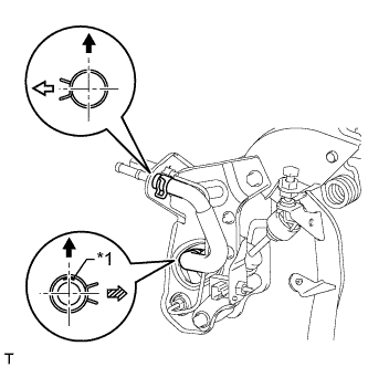
Text in Illustration *1 Paint Mark 
Top 
Left 
Rear Connect the clutch reservoir hose.
Tech Tips
-
Make sure the paint mark of the clutch reservoir hose is facing upward.
-
Make sure the direction of the clamp is as shown in the illustration.
-
-
-
INSTALL CLUTCH PEDAL WITH CLUTCH MASTER CYLINDER
-
Install the clutch pedal with clutch master cylinder to the vehicle with the 2 nuts and bolt.
- Torque:
- for nut
- 16 N*m { 163 kgf*cm, 12 ft.*lbf }
- for bolt
- 18 N*m { 184 kgf*cm, 13 ft.*lbf }
-
w/ Cruise Control:
Connect the clutch switch connector.
-
Connect the clutch start switch connector.
-
-
INSTALL DRIVER SIDE JUNCTION BLOCK ASSEMBLY
-
Install the driver side junction block Click here.
-
-
CONNECT CLUTCH MASTER CYLINDER TO FLEXIBLE HOSE TUBE
-
Using a union nut wrench, connect the flexible hose tube.
- Torque:
- 15 N*m { 155 kgf*cm, 11 ft.*lbf }
Note
Use the formula to calculate special torque values for situations where a union nut wrench is combined with a torque wrench Click here.
-
-
CONNECT CLUTCH RESERVOIR TUBE
-
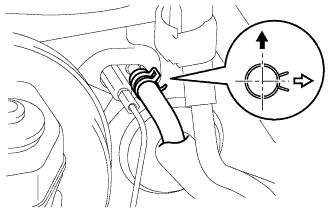
Connect the clutch reservoir tube.
Text in Illustration Top Left Tech Tips
Make sure the direction of the clamp is as shown in the illustration.
-
-
FILL RESERVOIR WITH BRAKE FLUID
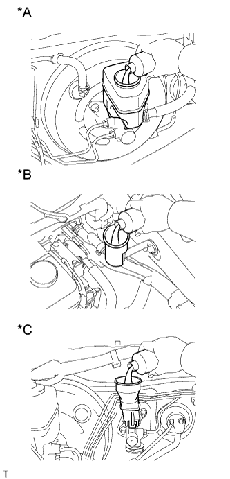
Text in Illustration *A for LHD (2TR-FE, 5L-E) *B for LHD (1GR-FE, 1KD-FTV) *C for RHD
-
Fill the reservoir with brake fluid.
Brake fluid SAE J1703 or FMVSS No. 116 DOT 3
-
-
BLEED CLUTCH LINE
-
Remove the bleeder plug cap of the release cylinder.
-
Connect a vinyl tube to the bleeder plug.
-
Depress the clutch pedal several times, and then loosen the bleeder plug while the pedal is depressed.
-
When fluid no longer comes out, tighten the bleeder plug, and then release the clutch pedal.
-
Repeat the previous 2 steps until all the air in the fluid is completely bled.
-
Tighten the bleeder plug.
- Torque:
- 11 N*m { 110 kgf*cm, 8 ft.*lbf }
-
Install the bleeder plug cap.
-
Check that all the air has been bled from the clutch line.
-
-
CHECK FLUID LEVEL IN RESERVOIR
-
Check the fluid level.
If the brake fluid level is low, check for leaks and inspect the disc brake pad. If necessary, refill the reservoir with brake fluid after repair or replacement.
Brake fluid SAE J1703 or FMVSS No. 116 DOT 3
-
-
CHECK FOR BRAKE FLUID LEAK FROM CLUTCH LINE
-
INSPECT AND ADJUST CLUTCH PEDAL SUB-ASSEMBLY
-
Fold back the floor carpet.
-
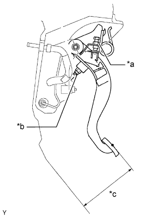
Text in Illustration *a Pedal Height Adjustment Point *b Push Rod Play and Free Play Adjustment Point *c Pedal Height Check that the pedal height is correct.
Pedal height from floor 172.9 to 182.9 mm (6.81 to 7.20 in.) -
Adjust the pedal height.
-
w/ Cruise Control:
Loosen the lock nut and turn the clutch switch until the height is correct. Tighten the lock nut.
- Torque:
- 16 N*m { 160 kgf*cm, 12 ft.*lbf }
-
w/o Cruise Control:
Loosen the lock nut and turn the clutch pedal stopper bolt until the height is correct. Tighten the lock nut.
- Torque:
- 26 N*m { 260 kgf*cm, 19 ft.*lbf }
-
-
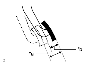
Text in Illustration *a Pedal Free Play *b Push Rod Play Check the pedal free play and push rod play.
Tech Tips
Pay close attention to the change in resistance to distinguish between pedal free play and push rod play while performing the inspection.
-
Depress the clutch pedal until resistance is felt.
-
Measure the distance between the pedal's released position and the position in the previous step.
Pedal free play 5.0 to 15.0 mm (0.197 to 0.591 in.) -
Release the pedal. Using your finger, gently press the pedal until resistance increases slightly.
-
Measure the distance between the pedal's released position and the position in the previous step.
Push rod play at pedal top 1.0 to 5.0 mm (0.0394 to 0.197 in.)
-
-
Adjust the pedal free play and push rod play.
Tech Tips
The push rod play can be adjusted by changing the length of the push rod. Pedal free play changes together with push rod play.
-
Loosen the lock nut and turn the push rod until the pedal free play and push rod play are within the specified ranges.
Note
If pedal free play and push rod play are not within the standard range even after adjustment, inspect the related parts.
-
Tighten the lock nut.
- Torque:
- 12 N*m { 120 kgf*cm, 9 ft.*lbf }
-
After adjusting the pedal free play and push rod play, check the pedal height.
-
-
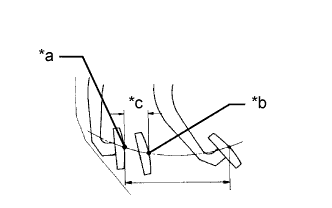
Text in Illustration *a Full Stroke End Position *b Release Position *c 25 mm or more Check the clutch release point.
-
Pull the parking brake lever and use wheel chocks to stabilize the vehicle.
-
Start the engine and run it at idle.
-
Without depressing the clutch pedal, slowly move the shift lever to R until the gears contact.
-
Gently depress the clutch pedal and measure the stroke distance from the point that the gear noise stops (release point) up to the full stroke end position.
Standard distance 25 mm (0.984 in.) or more If the result is not as specified, perform the following procedures.
-
Check pedal height.
-
Check push rod play and pedal free play.
-
Bleed air from clutch line.
-
Check clutch cover and disc.
-
-
-