PARK / NEUTRAL POSITION SWITCH INSTALLATION

-
INSTALL PARK/NEUTRAL POSITION SWITCH ASSEMBLY
Tech Tips
Make sure that the manual valve lever shaft has not been rotated prior to installing the park/neutral position switch as the detent spring may become detached from the manual valve lever shaft.
-
Clean the bolt and the bolt hole.
-
Apply adhesive to 2 or 3 threads on the end of the bolt.
Adhesive Toyota Genuine Adhesive 1344, Three Bond 1344 or equivalent -
Install the park/neutral position switch assembly to the manual valve shaft.
-
Temporarily install the bolt.
-
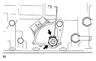
Text in Illustration *1 New Lock Washer Install a new lock washer and the nut.
- Torque:
- 6.9 N*m { 70 kgf*cm, 61 in.*lbf }
-
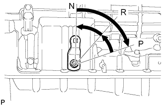
Turn the control shaft lever LH clockwise until it stops, and then turn it counterclockwise 2 notches to set it to the N position.
-
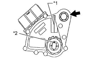
Text in Illustration *1 Neutral Basic Line *2 Groove Align the groove with the neutral basic line.
-
Hold the switch in position and tighten the bolt.
- Torque:
- 13 N*m { 130 kgf*cm, 9 ft.*lbf }
-
Using a screwdriver, bend the tabs of the lock washer.
-
Connect the park/neutral position switch connector.
-
-
INSPECT SHIFT LEVER POSITION
Text in Illustration *a Component without harness connected
(Transmission Control Switch)
-
Measure the resistance according to the value(s) in the table below.
Standard Resistance Tester Connection Condition Specified Condition 3 (IG) - 7 (S) Shift lever in S, "+" or "-" Below 1 Ω 3 (IG) - 7 (S) Shift lever not in S, "+" or "-" 10 kΩ or higher If the result is not as specified, replace the transmission floor shift assembly.
-
-
INSPECT PARK/NEUTRAL POSITION SWITCH ASSEMBLY
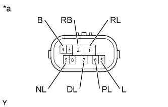
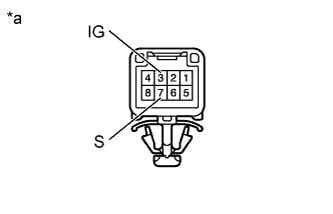
Text in Illustration *a Component without harness connected
(Park/Neutral Position Switch)
-
Measure the resistance according to the value(s) in the table below.
Standard Resistance Tester Connection Condition Specified Condition
-
2 (RB) - 6 (PL)
-
4 (B) - 5 (L)
Shift lever in P Below 1 Ω 2 (RB) - 1 (RL) Shift lever in R Below 1 Ω
-
2 (RB) - 9 (NL)
-
4 (B) - 5 (L)
Shift lever in N Below 1 Ω 2 (RB) - 7 (DL)
-
Shift lever in D
-
Shift lever in S, "+" or "-"
Below 1 Ω
-
2 (RB) - 6 (PL)
-
4 (B) - 5 (L)
Shift lever not in P 10 kΩ or higher 2 (RB) - 1 (RL) Shift lever not in R 10 kΩ or higher
-
2 (RB) - 9 (NL)
-
4 (B) - 5 (L)
Shift lever not in N 10 kΩ or higher 2 (RB) - 7 (DL)
-
Shift lever not in D
-
Shift lever not in S, "+" or "-"
10 kΩ or higher If the result is not as specified, replace the switch.
-
-
-
INSTALL FRONT EXHAUST PIPE ASSEMBLY (w/ DPF)
-
Install a new gasket and the front exhaust pipe to the No. 2 turbine outlet elbow with 3 new nuts.
- Torque:
- 54 N*m { 554 kgf*cm, 40 ft.*lbf }
-
Connect the front exhaust pipe to the 2 exhaust pipe supports.
Tech Tips
Install the exhaust pipe supports after installing the No. 3 frame crossmember.
-
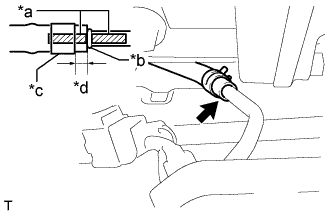
Text in Illustration *a Paint Mark *b Stopper *c Clip *d 4 to 10 mm (0.157 to 0.394 in.) Connect the No. 7 exhaust pipe air hose to the front exhaust pipe with a new clip.
Note
-
Align the paint marks of the front exhaust pipe and No. 7 exhaust pipe air hose and insert the No. 7 exhaust pipe air hose until it contacts the stopper.
-
Make sure the clip is 4 to 10 mm (0.157 to 0.394 in.) from the end of the No. 7 exhaust pipe air hose when installing the clip.
-
Make sure that there is no slack in the No. 7 exhaust pipe air hose, and that it is not twisted or bent.
-
Take care not to damage the inner or outer surface of the No. 7 exhaust pipe air hose when installing it. If the No. 7 exhaust pipe air hose is damaged, replace it with a new one.
-
-
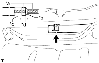
Text in Illustration *a Paint Mark *b Stopper *c Clip *d 4 to 10 mm (0.157 to 0.394 in.) Connect the No. 6 exhaust pipe air hose to the front exhaust pipe with a new clip.
Note
-
Align the paint marks of the front exhaust pipe and No. 6 exhaust pipe air hose and insert the No. 6 exhaust pipe air hose until it contacts the stopper.
-
Make sure the clip is 4 to 10 mm (0.157 to 0.394 in.) from the end of the exhaust pipe air hose when installing the clip.
-
Make sure that there is no slack in the No. 6 exhaust pipe air hose, and that it is not twisted or bent.
-
Take care not to damage the inner or outer surface of the No. 6 exhaust pipe air hose when installing it. If the No. 6 exhaust pipe air hose is damaged, replace it with a new one.
-
-
Connect the No. 3 exhaust gas temperature sensor connector.
-
Connect the No. 2 exhaust gas temperature sensor connector.
-
Connect the exhaust gas temperature sensor connector.
-
-
CONNECT CENTER EXHAUST PIPE ASSEMBLY (w/ DPF)
-
Using a vernier caliper, measure the free length of the compression spring.
Minimum free length 43 mm (1.693 in.) If the free length is less than the minimum, replace the compression spring.
-
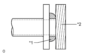
Text in Illustration *1 Gasket *2 Wooden Block Using a plastic-faced hammer and wooden block, tap in a new gasket until its surface is flush with the front exhaust pipe.
Note
-
Be sure to install the gasket so that it faces the correct direction.
-
Do not reuse the gasket.
-
Do not damage the gasket.
-
When connecting the exhaust pipe, do not push in the gasket with the exhaust pipe.
-
-
Connect the center exhaust pipe assembly and install the 2 compression springs with the 2 bolts.
-
-
CONNECT AIR FUEL RATIO SENSOR (w/ DPF)
-
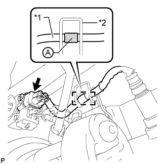
Text in Illustration *1 Wire Harness *2 Clamp Connect the air fuel ratio sensor connector and attach the clamp.
Tech Tips
Make sure that the part of the wire harness labeled A is as shown in the illustration.
-
-
INSTALL NO. 3 FRAME CROSSMEMBER SUB-ASSEMBLY (w/ DPF)
-
Install the frame crossmember to the engine mounting insulator with the 4 set bolts.
- Torque:
- 30 N*m { 306 kgf*cm, 22 ft.*lbf }
-
Connect the ends of the frame crossmember to the vehicle with the 4 bolts and 4 nuts.
- Torque:
- 72 N*m { 734 kgf*cm, 53 ft.*lbf }
-
-
INSTALL FRONT SUSPENSION MEMBER BRACKET LH AND RH (w/ DPF)
-
Install the front suspension member bracket LH and front suspension member bracket RH with the 8 bolts.
- Torque:
- 33 N*m { 337 kgf*cm, 24 ft.*lbf }
-
-
INSPECT FOR EXHAUST GAS LEAK (w/ DPF)
-
If gas is leaking, tighten the areas necessary to stop the leak. Replace damaged parts as necessary.
-