AUTOMATIC TRANSMISSION UNIT INSPECTION

-
INSPECT AUTOMATIC TRANSMISSION OIL PAN SUB-ASSEMBLY
-
Remove the magnets and use them to collect steel particles.
-
Carefully look at the foreign matter and particles in the pan and on the magnets to anticipate the type of wear you will find in the transmission.
-
Steel (magnetic): bearing, gear and clutch plate wear.
-
Brass (non-magnetic): bush wear.
-
-
-
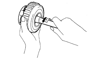
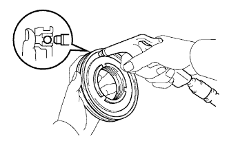
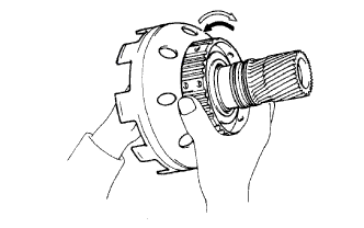
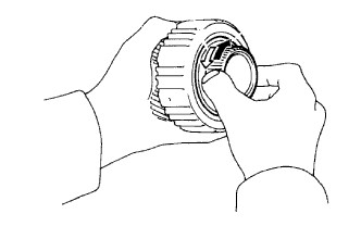
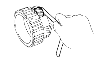
INSPECT OVERDRIVE 1-WAY CLUTCH
-
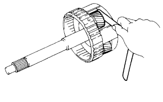
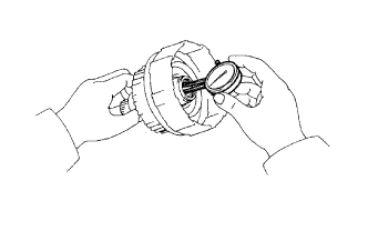
Hold the overdrive direct clutch drum and turn the input shaft. Check that the input shaft can be turned clockwise freely and locks when turned counterclockwise.
Text in Illustration 
Lock 
Free
-
-
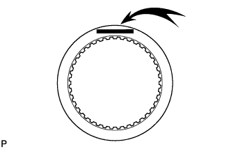
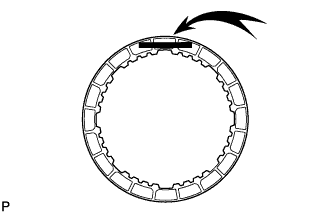
INSPECT OVERDRIVE DIRECT CLUTCH DISC

-
Replace all the discs if one of the following problems is present: 1) a disc, plate or flange is worn or burnt, 2) the lining of a disc is peeled off or discolored, or 3) the grooves or printed numbers have even a little bit of damage.
Note
When assembling new discs, soak them in ATF for at least 15 minutes before assembly.
-
-
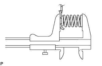
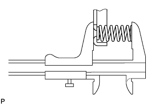
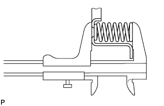
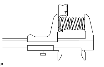
INSPECT OVERDRIVE CLUTCH RETURN SPRING SUB-ASSEMBLY
-
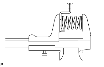
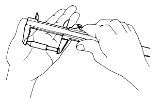
Using a vernier caliper, measure the free length of the spring together with the spring seat.
Standard free length 15.8 mm (0.622 in.) If the length is not as specified, replace the overdrive clutch return spring sub-assembly.
-
-
INSPECT OVERDRIVE DIRECT CLUTCH PISTON SUB-ASSEMBLY
-
Check that the check ball is free by shaking the piston.
-
Check that the valve does not have leaks by applying low-pressure compressed air.
If the result is not as specified, replace the overdrive direct clutch piston sub-assembly.
-
-
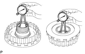
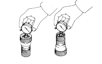
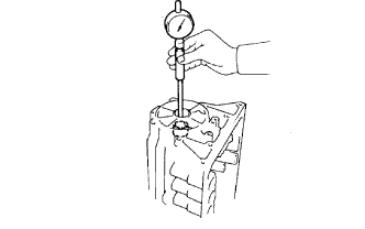
INSPECT OVERDRIVE DIRECT CLUTCH DRUM SUB-ASSEMBLY
-
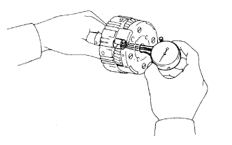
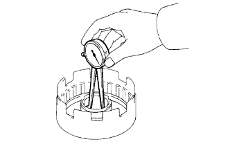
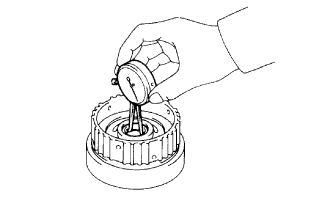
Using a dial indicator, measure the inside diameter of the clutch drum bushes.
Maximum inside diameter 27.11 mm (1.07 in.) If the inside diameter is more than the maximum, replace the overdrive direct clutch drum sub-assembly.
-
-
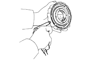
INSPECT OVERDRIVE PLANETARY GEAR ASSEMBLY
-
Using a dial indicator, measure the inside diameter of the planetary gear bush.
Maximum inside diameter 11.2 to 11.221 mm (0.441 to 0.442 in.) If the inside diameter is more than the maximum, replace the overdrive planetary gear assembly.
-
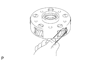
Using a feeler gauge, measure the planetary pinion gear thrust clearance.
Standard clearance 0.20 to 0.60 mm (0.00787 to 0.0236 in.) Maximum clearance 0.65 mm (0.0256 in.) If the clearance is more than the maximum, replace the overdrive planetary gear assembly.
-
-
INSPECT OVERDRIVE BRAKE DISC

-
Replace all the discs if one of the following problems is present: 1) a disc, plate or flange is worn or burnt, 2) the lining of a disc is peeled off or discolored, or 3) the grooves or printed numbers have even a little bit of damage.
Note
When assembling new discs, soak them in ATF for at least 15 minutes before assembly.
-
-
INSPECT PISTON OPERATION OF OVERDRIVE BRAKE
-
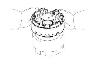
Place the overdrive support assembly to the direct clutch assembly.
-
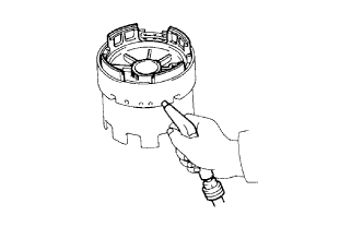
Apply compressed air (392 kPa (4 kgf/cm2, 57 psi)) into the oil passage and check that the overdrive brake piston moves smoothly.
-
-
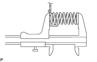
INSPECT OVERDRIVE BRAKE RETURN SPRING SUB-ASSEMBLY
-
Using a vernier caliper, measure the free length of the spring together with the spring seat.
Standard free length 17.03 mm (0.671 in.) If the length is not as specified, replace the overdrive brake return spring sub-assembly.
-
-
INSPECT DIRECT CLUTCH DISC
-
Replace all the discs if one of the following problems is present: 1) a disc, plate or flange is worn or burnt, 2) the lining of a disc is peeled off or discolored, or 3) the grooves or printed numbers have even a little bit of damage.
Note
When assembling new discs, soak them in ATF for at least 15 minutes before assembly.
-
-
INSPECT DIRECT CLUTCH RETURN SPRING SUB-ASSEMBLY
-
Using a vernier caliper, measure the free length of the spring together with the spring seat.
Standard free length 21.32 mm (0.839 in.) If the length is not as specified, replace the direct clutch return spring sub-assembly.
-
-
INSPECT DIRECT CLUTCH PISTON SUB-ASSEMBLY
-
Check that the check ball is free by shaking the piston.
-
Check that the valve does not have leaks by applying low-pressure compressed air.
-
-
INSPECT DIRECT CLUTCH DRUM SUB-ASSEMBLY
-
Using a dial indicator, measure the inside diameter of the clutch drum bush.
Standard inside diameter 53.915 to 53.94 mm (2.123 to 2.124 in.) Maximum inside diameter 53.99 mm (2.13 in.) If the inside diameter is more than the maximum, replace the direct clutch drum sub-assembly.
-
-
INSPECT FORWARD CLUTCH DISC
-
Replace all the discs if one of the following problems is present: 1) a disc, plate or flange is worn or burnt, 2) the lining of a disc is peeled off or discolored, or 3) the grooves or printed numbers have even a little bit of damage.
Note
When assembling new discs, soak them in ATF for at least 15 minutes before assembly.
-
-
INSPECT FORWARD CLUTCH PISTON SUB-ASSEMBLY
-
Check that the check ball is free by shaking the piston.
-
Check that the valve does not have leaks by applying low-pressure compressed air.
-
-
INSPECT INPUT SHAFT SUB-ASSEMBLY
-
Using a dial indicator, measure the inside diameter of the input shaft bush.
Standard inside diameter 24.0 to 24.026 mm (0.945 to 0.946 in.) Maximum inside diameter 24.076 mm (0.948 in.) If the inside diameter is more than the maximum, replace the input shaft sub-assembly.
-
-
INSPECT FORWARD CLUTCH RETURN SPRING SUB-ASSEMBLY
-
Using a vernier caliper, measure the free length of the spring together with the spring seat.
Standard free length 19.47 mm (0.767 in.) If the length is not as specified, replace the forward clutch return spring sub-assembly.
-
-
INSPECT SECOND COAST BRAKE PISTON ROD
-
Check the piston rod length.
Tech Tips
There are 2 different standard lengths for the piston rod.
Piston Rod Length Groove Mark Length Without 78.3 to 78.5 mm (3.08 to 3.09 in.) With 79.8 to 80.0 mm (3.14 to 3.15 in.) If the length is not as specified, replace the rod with a new one even if the brake band works normally.
-
-
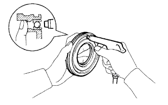
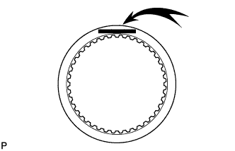
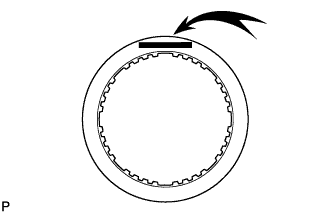
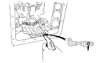
INSPECT SECOND COAST BRAKE BAND ASSEMBLY
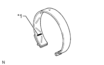
Text in Illustration *1 Printed Number Note
-
If the lining of the brake band is peeled off or discolored, or if any part of the printed numbers are damaged, replace the brake band.
-
When installing a new band, soak it in ATF for at least 15 minutes before installation.
-
-
INSPECT FRONT PLANETARY RING GEAR SUB-ASSEMBLY
-
Using a dial indicator, measure the inside diameter of the planetary ring gear bush.
Standard inside diameter 24.0 to 24.026 mm (0.945 to 0.946 in.) Maximum inside diameter 24.076 mm (0.948 in.) If the inside diameter is more than the maximum, replace the front planetary ring gear sub-assembly.
-
-
INSPECT FRONT PLANETARY GEAR ASSEMBLY
-
Using a feeler gauge, measure the pinion gear thrust clearance.
Standard clearance 0.20 to 0.60 mm (0.00787 to 0.0236 in.) Maximum clearance 0.65 mm (0.0256 in.) If the clearance is more than the maximum, replace the front planetary gear assembly.
-
-
INSPECT NO. 1 1-WAY CLUTCH ASSEMBLY
-
Hold the planetary sun gear, and turn the 1-way clutch assembly. Check that the 1-way clutch hub can be turned clockwise freely and locks when turned counterclockwise.
Text in Illustration Lock Free
-
-
INSPECT PLANETARY SUN GEAR SUB-ASSEMBLY
-
Using a dial indicator, measure the inside diameter of the planetary sun gear bushes.
Standard inside diameter 27.00 to 27.026 mm (1.063 to 1.064 in.) Maximum inside diameter 27.076 mm (1.07 in.) If the inside diameter is more than the maximum, replace the planetary sun gear sub-assembly.
-
-
INSPECT SECOND BRAKE PISTON
-
Check that the second brake piston moves smoothly when applying compressed air to and releasing low-pressure compressed air from the second brake drum.
-
-
INSPECT SECOND BRAKE DISC
-
Replace all the discs if one of the following problems is present: 1) a disc, plate or flange is worn or burnt, 2) the lining of a disc is peeled off or discolored, or 3) the grooves or printed numbers have even a little bit of damage.
Note
When assembling new discs, soak them in ATF for at least 15 minutes before assembly.
-
-
INSPECT SECOND BRAKE PISTON RETURN SPRING SUB-ASSEMBLY
-
Using a vernier caliper, measure the free length of the spring together with the spring seat.
Standard free length 16.05 mm (0.632 in.) If the length is not as specified, replace the second brake piston return spring sub-assembly.
-
-
INSPECT FIRST AND REVERSE BRAKE DISC
-
Replace all the discs if one of the following problems is present: 1) a disc, plate or flange is worn or burnt, 2) the lining of a disc is peeled off or discolored, or 3) the grooves or printed numbers have even a little bit of damage.
Note
When assembling new discs, soak them in ATF for at least 15 minutes before assembly.
-
-
INSPECT NO. 2 1-WAY CLUTCH
-
Hold the planetary gear and turn the 1-way clutch inner race. Check that the 1-way clutch inner race can be turned counterclockwise freely and locks when turned clockwise.
Text in Illustration Lock Free
-
-
INSPECT REAR PLANETARY GEAR ASSEMBLY
-
Using a feeler gauge, measure the thrust clearance.
Standard clearance 0.20 to 0.60 mm (0.00797 to 0.0236 in.) Maximum clearance 0.65 mm (0.0256 in.) If the clearance is more than the maximum, replace the rear planetary gear assembly.
-
-
INSPECT FIRST AND REVERSE BRAKE RETURN SPRING SUB-ASSEMBLY
-
Using a vernier caliper, measure the free length of the spring together with the spring seat.
Standard free length 18.182 to 18.582 mm (0.716 to 0.732 in.) If the length is not as specified, replace the first and reverse brake return spring sub-assembly.
-
-
INSPECT TRANSMISSION CASE BUSH
-
Using a cylinder gauge, measure the inside diameter of the transmission case rear bush.
Standard inside diameter 38.113 to 38.138 mm (1.5005 to 1.5014 in.) Maximum inside diameter 38.19 mm (1.50 in.) If the inside diameter is more than the maximum, replace the automatic transmission case sub-assembly.
-
-
INSPECT PISTON OPERATION OF FIRST AND REVERSE BRAKE
-
Make sure the first and reverse brake pistons move smoothly when compressed air is applied into the transmission case.
-
-
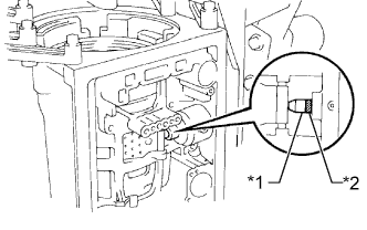
INSPECT PISTON OPERATION OF SECOND COAST BRAKE
-
Place a mark on the 2nd coast brake piston rod.
Text in Illustration *1 Mark *2 Piston Rod -
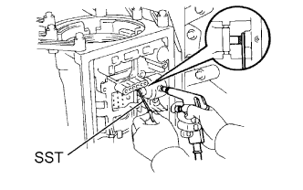
Using SST, measure the stroke while applying and releasing compressed air (392 kPa (4.0 kgf/cm2, 57 psi)).
- SST
- 09240-00020
Standard piston stroke 1.5 to 3.0 mm (0.059 to 0.118 in.) If the stroke is not as specified, replace the brake band with a new one.
-
-
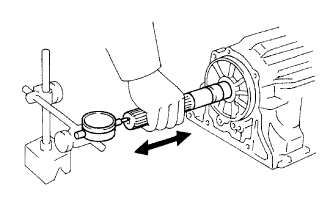
INSPECT OUTPUT SHAFT END PLAY
-
Using a dial indicator, measure the end play of the output shaft while moving it by hand.
Standard end play 0.30 to 1.04 mm (0.0118 to 0.0409 in.) If the end play is not as specified, check for improper installation.
-
Check that the output shaft rotates smoothly.
-