OIL COOLER INSTALLATION

-
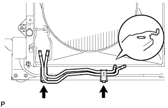
INSTALL NO. 2 OIL COOLER TUBE SUB-ASSEMBLY
-
Install the No. 2 oil cooler tube with the 2 bolts.
- Torque:
- 14 N*m { 143 kgf*cm, 10 ft.*lbf }
Note
Make sure the rotation stopper of the tube contacts the crossmember.
-
-
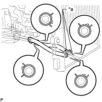
INSTALL NO. 2 OIL COOLER INLET HOSE AND NO. 2 OIL COOLER OUTLET HOSE
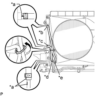
Text in Illustration *a Paint Mark *b Yellow Paint Mark *c Green Paint Mark *d Blue Paint Mark *e Pink Paint Mark
-
Connect the No. 2 oil cooler inlet hose and No. 2 oil cooler outlet hose to the No. 2 oil cooler tube.
-
Connect the 2 hoses to the radiator to install them, and then pass the 2 hoses through the No. 1 flexible hose clamp and close the clamp.
Note
-
When connecting the hoses to the tube, support the tube by hand and be careful to prevent the tube from being deformed.
-
Make sure the paint marks and pinching portion of each clip are facing the directions shown in the illustration.
-
-
-
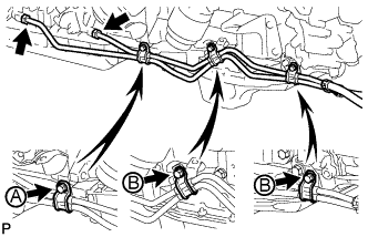
INSTALL NO. 1 OIL COOLER INLET TUBE AND NO. 1 OIL COOLER OUTLET TUBE
-
Temporarily install the 2 end of the oil cooler tubes to each oil cooler tube union by hand.
-
Close the 3 No. 2 flexible hose clamps and install the 3 bolts.
- Torque:
- for bolt A
- 14 N*m { 143 kgf*cm, 10 ft.*lbf }
- for bolt B
- 5.5 N*m { 56 kgf*cm, 49 in.*lbf }
-
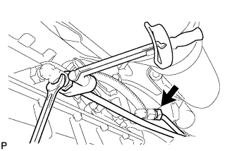
Using a union nut wrench, tighten the oil cooler tubes.
- Torque:
- 34 N*m { 347 kgf*cm, 25 ft.*lbf }
Note
Use the formula to calculate special torque values for situations where a union nut wrench is combined with a torque wrench Click here.
-
-
INSTALL NO. 1 OIL COOLER INLET HOSE AND NO. 1 OIL COOLER OUTLET HOSE
Text in Illustration *a Pink Paint Mark
-
Connect the No. 1 oil cooler inlet hose and No. 1 oil cooler outlet hose to the oil cooler inlet tube and No. 1 oil cooler outlet tube.
-
Connect the 2 hoses to the No. 2 oil cooler tube to install them.
Note
-
When connecting the hoses to the tube, support the tube by hand and be careful to prevent the tube from being deformed.
-
Make sure the paint marks and pinching portion of each clip are facing the directions shown in the illustration.
-
-
-
ADJUST AUTOMATIC TRANSMISSION FLUID LEVEL
-
Adjust the automatic transmission fluid level Click here.
-
-
INSTALL FRONT NO. 1 FENDER APRON TO FRAME SEAL RH
-
Install the front No. 1 fender apron to frame seal with the 5 clips.
-
-
INSTALL FRONT FENDER APRON SEAL RH
-
Install the front fender apron seal RH with the 5 clips.
-
-
INSTALL REAR ENGINE UNDER COVER ASSEMBLY
-
Install the rear engine under cover with the 4 bolts.
- Torque:
- 29 N*m { 296 kgf*cm, 21 ft.*lbf }
-
-
INSTALL NO. 1 ENGINE UNDER COVER SUB-ASSEMBLY
-
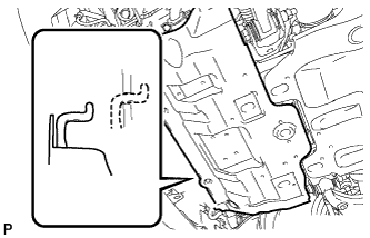
Hook the engine under cover to the vehicle body as shown in the illustration.
-
Install the 4 bolts.
- Torque:
- 29 N*m { 296 kgf*cm, 21 ft.*lbf }
-