AUTOMATIC TRANSMISSION ASSEMBLY INSTALLATION

-
INSPECT TORQUE CONVERTER CLUTCH ASSEMBLY
-
Inspect the torque converter clutch Click here.
-
-
INSTALL TORQUE CONVERTER CLUTCH ASSEMBLY
-
Install the torque converter clutch to the automatic transmission.
-
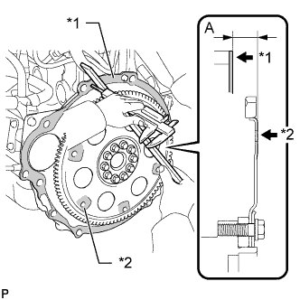
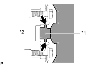
Using a vernier caliper and straightedge, measure dimension "A" between the transmission fitting surface of the engine*1 and the torque converter fitting surface of the drive plate*2 (step 1).
-
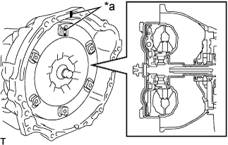
Text in Illustration *a Matchmark Aligning the matchmarks on the transmission case and torque converter clutch, and then mesh the splines of the input shaft and turbine runner.
-
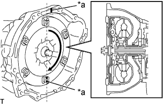
Text in Illustration *a Matchmark Mesh the splines of the stator shaft and stator while turning the torque converter clutch.
-
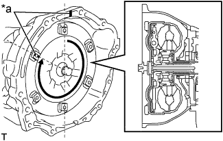
Text in Illustration *a Matchmark Turn the torque converter clutch to mesh the key of the oil pump drive gear into the slot on the torque converter clutch.
Note
Do not push on the torque converter when aligning the matchmarks.
-
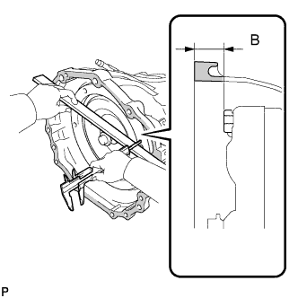
Using a vernier caliper and straightedge, measure dimension "B" shown in the illustration and check that B is more than A (measured in step 1).
Standard dimension B = A + 1.00 mm (0.0394 in.) or more
-
-
INSTALL TRANSFER ASSEMBLY
-
Install the transfer Click here.
-
-
INSTALL NO. 1 TRANSMISSION CONTROL CABLE BRACKET
-
Install the control cable bracket with the 2 bolts.
- Torque:
- 25 N*m { 255 kgf*cm, 18 ft.*lbf }
-
-
INSTALL AUTOMATIC TRANSMISSION ASSEMBLY
-
Apply clutch spline grease to the surface of the crankshaft that contacts the torque converter clutch centerpiece.
Clutch spline grease Toyota Genuine Clutch Spline Grease or equivalent Maximum grease amount Approximately 1 g (0.0353 oz.) Text in Illustration *1 Torque Converter Clutch Centerpiece *2 Crankshaft -
Confirm that the 2 knock pins are on the transmission contact surface of the engine block before transmission installation.
-
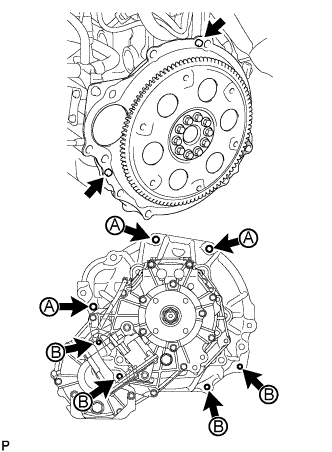
Install the transmission with the 7 bolts.
- Torque:
- for bolt A
- 71 N*m { 724 kgf*cm, 52 ft.*lbf, 17 mm head }
- for bolt B
- 37 N*m { 377 kgf*cm, 27 ft.*lbf, 14 mm head }
-
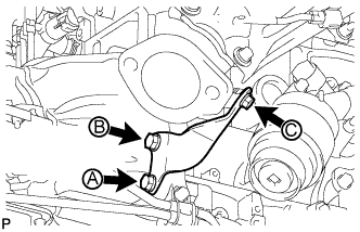
Install the exhaust manifold stay with the 3 bolts.
- Torque:
- for bolt A
- 71 N*m { 724 kgf*cm, 52 ft.*lbf }
- for bolt B
- 44 N*m { 449 kgf*cm, 32 ft.*lbf }
- for bolt C
- 30 N*m { 306 kgf*cm, 22 ft.*lbf }
-
-
INSTALL DRIVE PLATE AND TORQUE CONVERTER CLUTCH SETTING BOLT
-
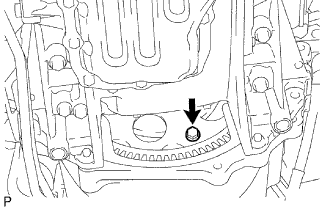
Turn the crankshaft to gain access to the installation locations of the 6 torque converter clutch setting bolts and install each bolt while holding the crankshaft pulley bolt with a wrench.
- Torque:
- 48 N*m { 489 kgf*cm, 35 ft.*lbf }
Note
Install the black bolt first, and then the 5 silver bolts.
-
Install the flywheel housing dust seal.
-
-
CONNECT WIRE HARNESS AND CONNECTOR
-
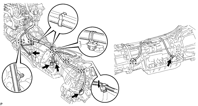
Connect the park/neutral position switch connector, transmission wire connector, 2 speed sensor connectors and transfer control side connector.
-
Attach the connector clamp and 5 harness clamps.
-
Tilt up the automatic transmission.
-
Connect the ground cable with the nut.
- Torque:
- 5.0 N*m { 51 kgf*cm, 44 in.*lbf }
-
-
CONNECT BREATHER HOSE
-
Connect the 2 transfer breather hoses to the engine.
-
-
INSTALL REAR NO. 1 ENGINE MOUNTING INSULATOR
-
Install the engine mounting insulator to the transmission with the 4 bolts.
- Torque:
- 65 N*m { 663 kgf*cm, 48 ft.*lbf }
-
Install the rear engine mounting heat insulator to the engine mounting insulator with the bolt.
- Torque:
- 12 N*m { 122 kgf*cm, 9 ft.*lbf }
-
-
INSTALL NO. 3 FRAME CROSSMEMBER SUB-ASSEMBLY
-
Install the frame crossmember to the rear engine mounting insulator with the 4 bolts.
- Torque:
- 30 N*m { 306 kgf*cm, 22 ft.*lbf }
-
Install the frame crossmember with the 4 bolts and 4 nuts.
- Torque:
- 72 N*m { 734 kgf*cm, 53 ft.*lbf }
-
-
INSTALL FRONT SUSPENSION MEMBER BRACKET LH AND RH
-
Install the front suspension member bracket LH and RH with the 8 bolts.
- Torque:
- 33 N*m { 337 kgf*cm, 24 ft.*lbf }
-
-
INSTALL STARTER ASSEMBLY
-
for 1.4 kW Type:
Install the starter Click here.
-
for 2.0 kW Type:
Install the starter Click here.
-
-
CONNECT TRANSMISSION CONTROL CABLE ASSEMBLY
-
Move the shift lever to P.
-
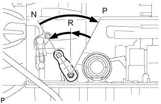
Turn the control shaft lever clockwise until it stops, and then turn it counterclockwise 2 notches to set it to the N position.
-
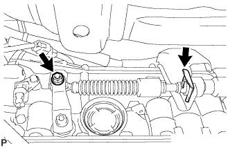
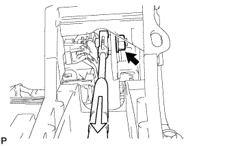
Connect the transmission control cable to the transmission control cable bracket with a new clip, and connect the cable end to the control shaft lever with the nut.
- Torque:
- 12 N*m { 122 kgf*cm, 9 ft.*lbf }
-
-
CONNECT NO. 1 OIL COOLER INLET TUBE AND NO. 1 OIL COOLER OUTLET TUBE
-
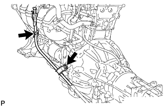
Temporarily install the 2 ends of the oil cooler tubes to each oil cooler tube union by hand.
-
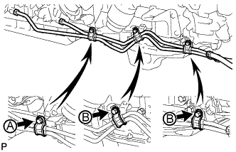
Close the 3 No. 2 oil cooler hose clamps and install the 3 bolts.
- Torque:
- for bolt A
- 14 N*m { 143 kgf*cm, 10 ft.*lbf }
- for bolt B
- 5.5 N*m { 56 kgf*cm, 49 in.*lbf }
-
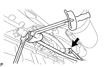
Using a union nut wrench, tighten the inlet and outlet tubes.
- Torque:
- 34 N*m { 347 kgf*cm, 25 ft.*lbf }
Note
Use the formula to calculate special torque values for situations where a union nut wrench is combined with a torque wrench Click here.
-
-
INSTALL TRANSMISSION OIL FILLER TUBE SUB-ASSEMBLY
-
Coat a new O-ring with ATF, and install it to the oil filler tube.
-
Install the oil filler tube to the transmission with the 2 bolts.
- Torque:
- 14 N*m { 143 kgf*cm, 10 ft.*lbf }
-
Install the oil dipstick.
-
-
INSTALL PROPELLER SHAFT ASSEMBLY
-
Install the propeller shaft Click here.
-
-
INSTALL FRONT PROPELLER SHAFT ASSEMBLY
-
Install the front propeller shaft Click here.
-
-
INSTALL TRANSFER CASE LOWER PROTECTOR
-
Install the transfer case lower protector with the 4 bolts.
- Torque:
- 18 N*m { 184 kgf*cm, 13 ft.*lbf }
-
-
INSTALL FRONT EXHAUST PIPE ASSEMBLY
-
Install the front exhaust pipe Click here.
-
-
ADD AUTOMATIC TRANSMISSION FLUID
Fluid type Toyota Genuine ATF WS -
CONNECT CABLE TO NEGATIVE BATTERY TERMINAL
Note
When disconnecting the cable, some systems need to be initialized after the cable is reconnected Click here.
-
ADJUST SHIFT LEVER POSITION
-
Remove the rear console box Click here.
-
w/ Refrigerated Cool Box:
Remove the rear console box Click here.
-
Move the shift lever to N.
-
Loosen the nut of the control cable end.
-
While pushing the control cable slightly toward the rear side of the vehicle, tighten the nut.
- Torque:
- 12 N*m { 122 kgf*cm, 9 ft.*lbf }
-
Move the shift lever and check that there is less wobble when moving the shift lever from N to D than when moving the shift lever to P.
-
Install the rear console box Click here.
-
w/ Refrigerated Cool Box:
Install the rear console box Click here.
-
-
INSPECT SHIFT LEVER POSITION
-
When moving the shift lever from P to R with the ignition switch to ON and the brake pedal depressed, make sure that it moves smoothly and correctly into position.
-
Check that the shift lever does not stop when moving the shift lever from R to P, and check that the shift lever does not stick when moving the shift lever from D to L.
-
Start the engine and make sure that the vehicle moves forward after moving the shift lever from N to D and moves in reverse after moving the shift lever to R.
If the operation cannot be performed as specified, inspect the park/neutral position switch assembly and check the transmission floor shift assembly installation condition.
If the indicator and shift lever position do not match, carry out the following adjustment procedures.
-
-
CHECK FOR EXHAUST GAS LEAK
-
INSPECT AUTOMATIC TRANSMISSION FLUID
-
Inspect the automatic transmission fluid Click here.
-
-
INSTALL FRONT NO. 1 FENDER APRON TO FRAME SEAL RH
-
Install the front No. 1 fender apron to frame seal with the 5 clips.
-
-
INSTALL FRONT FENDER APRON SEAL RH
-
Install the front fender apron seal RH with the 5 clips.
-
-
INSTALL REAR ENGINE UNDER COVER ASSEMBLY
-
Install the rear engine under cover with the 4 bolts.
- Torque:
- 29 N*m { 296 kgf*cm, 21 ft.*lbf }
-
-
INSTALL NO. 1 ENGINE UNDER COVER
-
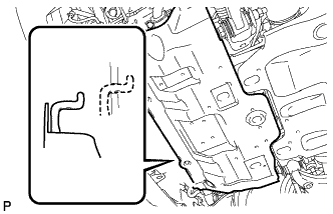
Hook the engine under cover to the vehicle body as shown in the illustration.
-
Install the 4 bolts.
- Torque:
- 29 N*m { 296 kgf*cm, 21 ft.*lbf }
-