AUTOMATIC TRANSMISSION SYSTEM, Diagnostic DTC:P2772

| DTC Code | DTC Name |
|---|---|
| P2772 | Four Wheel Drive (4WD) Low Switch Circuit Range / Performance |
DESCRIPTION
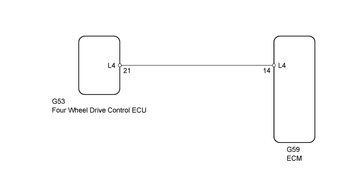
The ECM detects the signal from the transfer L4 position switch.
This DTC indicates that the transfer L4 position switch remains on.
| DTC Code | DTC Detection Condition | Trouble Area |
|---|---|---|
| P2772 | Transfer L4 position switch remains on while the vehicle is being driven under the following conditions for 1.8 sec. or more (1-trip detection logic): (a) Output shaft speed is between 1000 and 3000 rpm. (b) Transfer position switch is in H4. |
|
MONITOR DESCRIPTION
The ECM monitors the transfer-case L4 position switch to determine when the transfer-case L4 gears are engaged. If the L4 position switch indicates that the transfer-case L4 gears are engaged under the following conditions, the ECM will conclude that there is a malfunction of the L4 position switch, illuminate the MIL and store the DTC:
-
The transfer-case shifter is in the "H4" position.
-
The transfer-case output shaft speed is between 1000 and 3000 rpm.
-
The specified time period has elapsed.
WIRING DIAGRAM
INSPECTION PROCEDURE
PROCEDURE
-
CHECK HARNESS AND CONNECTOR (FOUR WHEEL DRIVE CONTROL ECU - BODY GROUND)
-
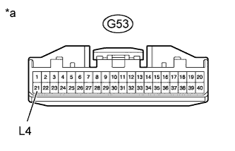
Text in Illustration *a Front view of wire harness connector
(to Four Wheel Drive Control ECU)
Disconnect the G53 four wheel drive control ECU connector.
-
Measure the resistance according to the value(s) in the table below.
Standard Resistance Tester Connection Condition Specified Condition G53-21 (L4) - Body ground Always 10 kΩ or higher
NG 
CHECK HARNESS AND CONNECTOR (FOUR WHEEL DRIVE CONTROL ECU - ECM) Click here
OK 
GO TO TRANSFER SYSTEM (TERMINALS OF ECU) Click here
-
-
CHECK HARNESS AND CONNECTOR (FOUR WHEEL DRIVE CONTROL ECU - ECM)
-
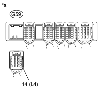
Text in Illustration *a Rear view of wire harness connector
(to ECM)
Disconnect the G59 ECM connector.
-
Measure the resistance according to the value(s) in the table below.
Standard Resistance Tester Connection Condition Specified Condition G59-14 (L4) - Body ground Always 10 kΩ or higher
NG 
REPAIR OR REPLACE HARNESS OR CONNECTOR
OK
REPLACE ECM Click here
-