DYNAMIC RADAR CRUISE CONTROL SYSTEM TERMINALS OF ECU

-
CHECK DRIVING SUPPORT ECU

Note
-
As disconnecting the connector to perform inspections may cause DTCs to be stored, clear DTCs after performing inspections.
-
As the connector may be damaged if a load of more than 10 kg (22 lb) is applied to it, do not apply any more load than necessary to the connector.
-
Disconnect the G119 ECU connector.
-
Measure the voltage and resistance according to the value(s) in the table below.
Terminal No. (Symbol) Wiring Color Terminal Description Condition Specified Condition G119-30 (B) - Body ground G - Body ground ECU power source circuit Ignition switch ON 11 to 14 V Ignition switch off Below 1 V G119-25 (GND) - Body ground BR - Body ground Ground Always Below 1 Ω If the result is not as specified, there may be a malfunction on the wire harness side.
-
Reconnect the G119 ECU connector.
-
Measure the voltage according to the value(s) in the table below.
Terminal No. (Symbol) Wiring Color Terminal Description Condition Specified Condition G119-7 (MODE) - Body ground SB - Body ground Distance control switch signal Ignition switch ON, distance control switch off 11 to 14 V Ignition switch ON, distance control switch on Below 1 V G119-32 (WIP2) - Body ground P - Body ground Windshield wiper switch circuit Ignition switch ON, windshield wiper switch Hi 11 to 14 V Ignition switch ON, windshield wiper switch Lo Approximately 9 V Ignition switch ON, windshield wiper switch off Below 1 V If the result is not as specified, the ECU may be malfunctioning.
-
-
CHECK ECM (for 1GR-FE)
-
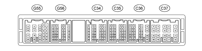
Disconnect the C36, G55 and G56 ECM connectors.
-
Measure the voltage and resistance according to the value(s) in the table below.
Terminal No. (Symbol) Wiring Color Terminal Description Condition Specified Condition G55-24 (BATT) - Body ground L - Body ground Power source circuit Always 11 to 14 V G56-21 (IGSW) - Body ground W - Body ground IG power source circuit Ignition switch ON 11 to 14 V Ignition switch off Below 1 V G55-8 (ST1-) - Body ground B - Body ground Stop light switch signal circuit Ignition switch ON, brake pedal released 11 to 14 V Ignition switch ON, brake pedal depressed Below 1 V G56-18 (STP) - Body ground V - Body ground Stop light switch signal circuit Brake pedal depressed 11 to 14 V Brake pedal released Below 1 V G56-11 (CCS) - Body ground B - Body ground Cruise control switch circuit Cruise control switch on Below 2.5 Ω Cruise control switch off 1 MΩ or higher +RES switch held on 235 to 245 Ω -SET switch held on 617 to 643 Ω CANCEL switch held on 1509 to 1571 Ω G56-17 (CCHG) - Body ground V - Body ground Cruise control switch circuit Cruise control switch on MODE switch held on Below 2.5 Ω Cruise control switch on MODE switch held off 1 MΩ or higher C36-12 (E1) - Body ground BR - Body ground Ground Always Below 1 Ω If the result is not as specified, there may be a malfunction on the wire harness side.
-
Reconnect the C36, G55 and G56 ECM connectors.
-
Measure the voltage according to the value(s) in the table below.
Terminal No. (Symbol) Wiring Color Terminal Description Condition Specified Condition G56-24 (S) - Body ground V - Body ground Transmission control switch circuit Ignition switch ON, shift lever in S 11 to 14 V Ignition switch ON, shift lever not in S Below 1 V G56-16 (SFTU) - Body ground GR - Body ground Transmission control switch circuit Ignition switch ON, shift lever in S → shift lever moved to "+" 11 to 14 V → Below 1 V G56-22 (SFTD) - Body ground LG - Body ground Transmission control switch circuit Ignition switch ON, shift lever in S → shift lever moved to "-" 11 to 14 V → Below 1 V C34-27 (D) - Body ground B - Body ground Park/neutral position switch signal Ignition switch ON, shift lever in D 11 to 14 V Ignition switch ON, shift lever not in D Below 1 V C34-35 (P) - Body ground L - Body ground Park/neutral position switch signal Ignition switch ON, shift lever in P 11 to 14 V Ignition switch ON, shift lever not in P Below 1 V C34-28 (R) - Body ground R - Body ground Park/neutral position switch signal Ignition switch ON, shift lever in R 11 to 14 V Ignition switch ON, shift lever not in R Below 1 V C34-29 (N) - Body ground G - Body ground Park/neutral position switch signal Ignition switch ON, shift lever in N 11 to 14 V Ignition switch ON, shift lever not in N Below 1 V If the result is not as specified, the ECM may be malfunctioning.
-
-
CHECK ECM (for 1KD-FTV)

-
Disconnect the C93, G57 and G58 ECM connectors.
-
Measure the voltage and resistance according to the value(s) in the table below.
Terminal No. (Symbol) Wiring Color Terminal Description Condition Specified Condition G57-23 (BATT) - Body ground L - Body ground Power source circuit Always 11 to 14 V G58-24 (IGSW) - Body ground W - Body ground IG power source circuit Ignition switch ON 11 to 14 V Ignition switch off Below 1 V G57-9 (ST1-) - Body ground B - Body ground Stop light switch signal circuit Ignition switch ON, brake pedal released 11 to 14 V Ignition switch ON, brake pedal depressed Below 1 V G57-8 (STP) - Body ground V - Body ground Stop light switch signal circuit Brake pedal depressed 11 to 14 V Brake pedal released Below 1 V G57-14 (CCS) - Body ground B - Body ground Cruise control switch circuit Cruise control switch on Below 2.5 Ω Cruise control switch off 1 MΩ or higher +RES switch held on 235 to 245 Ω -SET switch held on 617 to 643 Ω CANCEL switch held on 1509 to 1571 Ω G58-9 (CCHG) - Body ground V - Body ground Cruise control switch circuit Cruise control switch on MODE switch held on Below 2.5 Ω Cruise control switch on MODE switch held off 1 MΩ or higher C93-1 (E1) - Body ground BR - Body ground Ground Always Below 1 Ω If the result is not as specified, there may be a malfunction on the wire harness side.
-
-
CHECK TRANSMISSION CONTROL ECU (for 1KD-FTV)

-
Disconnect the G70 ECU connector.
-
Measure the voltage and resistance according to the value(s) in the table below.
Terminal No. (Symbol) Wiring Color Terminal Description Condition Specified Condition G70-5 (BATT) - Body ground L - Body ground Power source circuit Always 11 to 14 V G70-6 (IG2) - Body ground B - Body ground IG power source circuit Ignition switch ON 11 to 14 V Ignition switch off Below 1 V If the result is not as specified, there may be a malfunction on the wire harness side.
-
Reconnect the G70 ECU connector.
-
Measure the voltage according to the value(s) in the table below.
Terminal No. (Symbol) Wiring Color Terminal Description Condition Specified Condition G70-15 (S) - Body ground V - Body ground Transmission control switch circuit Ignition switch ON, shift lever in S 11 to 14 V Ignition switch ON, shift lever not in S Below 1 V G70-22 (SFTU) - Body ground GR - Body ground Transmission control switch circuit Ignition switch ON, shift lever in S → shift lever moved to "+" 11 to 14 V → Below 1 V G70-23 (SFTD) - Body ground LG - Body ground Transmission control switch circuit Ignition switch ON, shift lever in S → shift lever moved to "-" 11 to 14 V → Below 1 V G71-8 (D) - Body ground B - Body ground Park/neutral position switch signal Ignition switch ON, shift lever in D 11 to 14 V Ignition switch ON, shift lever not in D Below 1 V G69-13 (P) - Body ground L - Body ground Park/neutral position switch signal Ignition switch ON, shift lever in P 11 to 14 V Ignition switch ON, shift lever not in P Below 1 V G71-9 (R) - Body ground R - Body ground Park/neutral position switch signal Ignition switch ON, shift lever in R 11 to 14 V Ignition switch ON, shift lever not in R Below 1 V G69-14 (N) - Body ground G - Body ground Park/neutral position switch signal Ignition switch ON, shift lever in N 11 to 14 V Ignition switch ON, shift lever not in N Below 1 V If the result is not as specified, the ECU may be malfunctioning.
-