DYNAMIC RADAR CRUISE CONTROL SYSTEM, Diagnostic DTC:U0235

| DTC Code | DTC Name |
|---|---|
| U0235 | Lost Communication with Cruise Control Front Distance Range Sensor |
DESCRIPTION
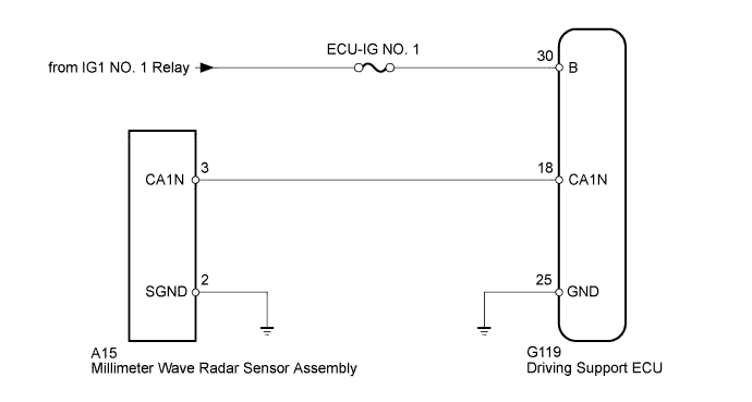
The millimeter wave radar sensor assembly and driving support ECU transmit the data for general vehicle control and the diagnosis function through the communication line.
The millimeter wave radar sensor assembly transmits information about the vehicle in front to the driving support ECU.
| DTC Code | DTC Detection Condition | Trouble Area |
|---|---|---|
| U0235 | While the vehicle speed is 50 km/h (31 mph) or more with the cruise control switch on, a communication stop between the millimeter wave radar sensor and driving support ECU continues for 1 second or more. |
|
WIRING DIAGRAM
INSPECTION PROCEDURE
Note
-
When the driving support ECU is replaced with a new one, initialization must be performed Click here.
-
Inspect the fuses for circuits related to this system before performing the following inspection procedure.
-
Confirm that the connector is securely connected, as a partially connected connector may be the cause of this DTC.
PROCEDURE
-
CHECK HARNESS AND CONNECTOR (DRIVING SUPPORT ECU - BATTERY AND BODY GROUND)
Note
A DTC is stored when the following inspection is performed. Be sure to clear the DTC after performing this inspection.
-
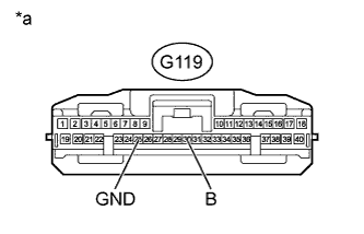
Text in Illustration *a Front view of wire harness connector
(to Driving Support ECU)
Disconnect the G119 ECU connector.
-
Measure the voltage according to the value(s) in the table below.
Standard Voltage Tester Connection Switch Condition Specified Condition G119-30 (B) - Body ground Ignition switch ON 11 to 14 V Ignition switch off Below 1 V -
Measure the resistance according to the value(s) in the table below.
Standard Resistance Tester Connection Condition Specified Condition G119-25 (GND) - Body ground Always Below 1 Ω
NG 
REPAIR OR REPLACE HARNESS OR CONNECTOR
OK 
-
-
CHECK HARNESS AND CONNECTOR (MILLIMETER WAVE RADAR SENSOR - BODY GROUND)
-
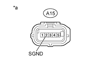
Text in Illustration *a Front view of wire harness connector
(to Millimeter Wave Radar Sensor Assembly)
Disconnect the A15 sensor connector.
-
Measure the resistance according to the value(s) in the table below.
Standard Resistance Tester Connection Condition Specified Condition A15-2 (SGND) - Body ground Always Below 1 Ω
NG
REPAIR OR REPLACE HARNESS OR CONNECTOR
OK
-
-
CHECK HARNESS AND CONNECTOR (DRIVING SUPPORT ECU - MILLIMETER WAVE RADAR SENSOR)
-
Disconnect the G119 ECU connector.
-
Disconnect the A15 sensor connector.
-
Measure the resistance according to the value(s) in the table below.
Standard Resistance Tester Connection Condition Specified Condition G119-18 (CA1N) - A15-3 (CA1N) Always Below 1 Ω G119-18 (CA1N) - Body ground Always 10 kΩ or higher
NG
REPAIR OR REPLACE HARNESS OR CONNECTOR
OK
-
-
CHECK DRIVING SUPPORT ECU
Note
A DTC is stored when the following inspection is performed. Be sure to clear the DTC after performing this inspection.
-
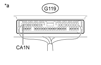
Text in Illustration *a Component with harness connected
(Driving Support ECU)
Disconnect the A15 sensor connector.
-
Measure the voltage according to the value(s) in the table below.
Standard Voltage Tester Connection Switch Condition Specified Condition G119-18 (CA1N) - Body ground Ignition switch ON 4.5 to 5.5 V
NG
REPLACE DRIVING SUPPORT ECU Click here
OK
-
-
REPLACE MILLIMETER WAVE RADAR SENSOR ASSEMBLY
-
Replace the millimeter wave radar sensor assembly Click here.
NEXT
-
-
ADJUST MILLIMETER WAVE RADAR SENSOR ASSEMBLY
-
Adjust the millimeter wave radar sensor assembly Click here.
NEXT
-
-
CHECK FOR DTC
-
Clear the DTCs Click here.
-
Perform the following to make sure the DTC detection conditions are met.
Tech Tips
If the detection conditions are not met, the system cannot detect the malfunction.
-
Drive the vehicle at a speed of 50 km/h (31 mph) or more.
-
Turn the cruise control switch on.
-
-
Check for DTCs Click here.
OK DTC U0235 is not output.
NG
REPLACE DRIVING SUPPORT ECU Click here
OK 
END (MILLIMETER WAVE RADAR SENSOR ASSEMBLY IS DEFECTIVE)
-