ENGINE OIL COOLER (w/o DPF) INSTALLATION

-
INSTALL OIL COOLER ASSEMBLY
-
Install 2 new gaskets to the oil cooler.
-
Install the oil cooler to the oil cooler cover with the 4 nuts.
- Torque:
- 16 N*m { 163 kgf*cm, 12 ft.*lbf }
-
-
INSTALL OIL COOLER COVER SUB-ASSEMBLY
-
Install a new gasket and the oil cooler cover with the 13 bolts.
- Torque:
- 13 N*m { 133 kgf*cm, 10 ft.*lbf }
-
Connect the No. 2 vacuum transmitting pipe with the 2 nuts.
- Torque:
- 13 N*m { 133 kgf*cm, 10 ft.*lbf }
-
Connect the vinyl tube.
-
Connect the oil pressure switch connector.
-
-
INSTALL OIL FILTER SUB-ASSEMBLY
-
Check and clean the oil filter installation surface.
-
Apply clean engine oil to the gasket of a new oil filter.
-
Lightly screw the oil filter into place by hand. Tighten it until the gasket contacts the seat.
-
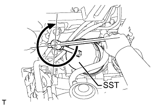
Using SST, tighten the oil filter. Depending on the space available, choose from the following.
- SST
- 09228-07501
-
If enough space is available, use a torque wrench to tighten the oil filter.
- Torque:
- 17 N*m { 173 kgf*cm, 13 ft.*lbf }
-
If enough space is not available to use a torque wrench, tighten the oil filter 3/4 of a turn by hand or with a common wrench.
-
-
CONNECT NO. 3 WATER BY-PASS HOSE (w/ EGR Cooler)
-
Connect the No. 3 water by-pass hose.
-
-
INSTALL VACUUM CONTROL VALVE SET
-
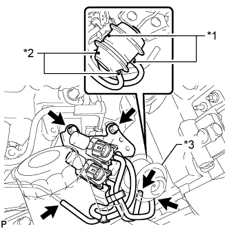
Text in Illustration *1 Paint Mark (White) *2 Paint Mark (Green) *3 Swirl Control Valve Actuator Install the vacuum control valve set with the 2 bolts.
- Torque:
- 20 N*m { 204 kgf*cm, 15 ft.*lbf }
-
Connect the 3 vacuum hoses and 2 VSV connectors.
Note
When connecting the hoses, match the colors of the paint marks on the hoses to the colors of the paint marks on the swirl control valve as shown in the illustration.
-
-
INSTALL SUPPLY PUMP ASSEMBLY
-
Install the supply pump Click here.
-
-
INSTALL COMMON RAIL ASSEMBLY
-
Install the common rail Click here.
-
-
INSTALL STARTER ASSEMBLY
-
for 2.2 kW Type:
Install the starter Click here.
-
for 2.7 kW Type:
Install the starter Click here.
-
for 3.0 kW Type:
Install the starter Click here.
-
-
ADD ENGINE OIL
-
Add new engine oil.
Standard Oil Grade Item Oil Grade Oil Viscosity (SAE) w/ DPF ACEA C2
(Using engine oil other than ACEA C2 may damage catalytic converter)
- 0W-30
- 5W-30
(0W-30 is best choice for fuel economy and good starting in cold weather)
w/o DPF G-DLD1, API CF-4, CF or ACEA B1
(You may also use API CE or CD)
- 5W-30
- 10W-30
- 15W-40
- 20W-50
Standard Capacity Item Specified Condition Drain and refill without oil filter change 6.7 liters (7.1 US qts, 5.9 Imp. qts) Drain and refill with oil filter change 7.0 liters (7.4 US qts, 6.2 Imp. qts) Dry fill 7.5 liters (7.9 US qts, 6.6 Imp. qts) -
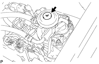
Install the oil filler cap.
-
-
BLEED AIR FROM FUEL SYSTEM
-
Using the hand pump mounted on the fuel filter cap, bleed the air from the fuel system. Continue pumping until the pump resistance increases.
Note
-
The maximum hand pump pumping speed is 2 strokes per second.
-
The hand pump must be pushed with a full stroke during pumping.
-
When the fuel pressure at the supply pump inlet port reaches a saturated pressure, the hand pump resistance increases.
-
If pumping is interrupted during the air bleeding process, fuel in the fuel line may return to the fuel tank. Continue pumping until the hand pump resistance increases.
-
If the hand pump resistance does not increase despite consecutively pumping 200 times or more, there may be a fuel leak between the fuel tank and fuel filter, the hand pump may be malfunctioning, or the vehicle may have run out of fuel.
-
If air bleeding using the hand pump is incomplete, the common rail pressure does not rise to the pressure range necessary for normal use and the engine cannot be started.
-
-
Start the engine.
Note
-
Even if air bleeding using the hand pump has been completed, the starter may need to be cranked for 10 seconds or more to start the engine.
-
Do not crank the engine continuously for more than 20 seconds. The battery may be discharged.
-
Use a fully-charged battery.
-
When the engine can be started, proceed to the next step.
-
If the engine cannot be started, bleed the air again using the hand pump until the hand pump resistance increases (refer to the procedures above). Then start the engine.
-
-
Turn the ignition switch off.
-
Connect the intelligent tester to the DLC3.
-
Turn the ignition switch on (IG) and turn the intelligent tester on.
-
Clear the DTCs Click here.
-
Start the engine.*1
-
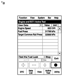
Text in Illustration *a Reference
Active Test Operation
Enter the following menus: Powertrain / Engine and ECT / Active Test / Test the Fuel Leak.*2
-
Perform the following test 5 times with on/off intervals of 10 seconds: Active Test / Test the Fuel Leak.*3
-
Allow the engine to idle for 3 minutes or more after performing the Active Test for the 5th time.
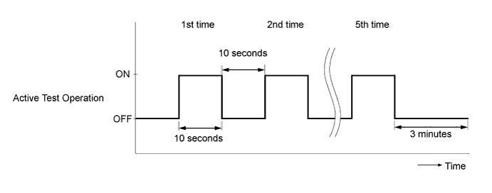
Tech Tips
When the Active Test "Test the Fuel Leak" is used to change the pump control mode, the actual fuel pressure inside the common rail drops below the target fuel pressure when the Active Test is off, but this is normal and does not indicate a pump malfunction.
-
Enter the following menus: Powertrain / Engine and ECT / DTC.
-
Read Current DTCs.
-
Clear the DTCs Click here.
Tech Tips
It is necessary to clear the DTCs as DTC P1604 or P1605 may be stored when air is bled from the fuel system after replacing or repairing fuel system parts.
-
Repeat steps *1 to *3.
-
Enter the following menus: Powertrain / Engine and ECT / DTC.
-
Read Current DTCs.
OK No DTCs are output.
-
-
ADD ENGINE COOLANT
-
Tighten the radiator drain cock plug by hand.
-
Tighten the cylinder block drain cock plug.
- Torque:
- 8.0 N*m { 82 kgf*cm, 71 in.*lbf }
-
Fill the radiator with TOYOTA Super Long Life Coolant (SLLC) to the B line of the reservoir tank.
Standard Capacity Item Specified Condition for Automatic Transmission w/ Rear Heater 14.9 liters (15.7 US qts, 13.1 Imp. qts) w/o Rear Heater 13.1 liters (13.8 US qts, 11.5 Imp. qts) for Manual Transmission w/ Rear Heater 15.0 liters (15.8 US qts, 13.2 Imp. qts) w/o Rear Heater 13.2 liters (13.9 US qts, 11.6 Imp. qts) Tech Tips
-
TOYOTA vehicles are filled with TOYOTA SLLC at the factory. In order to avoid damage to the engine cooling system and other technical problems, only use TOYOTA SLLC or similar high quality ethylene glycol based non-silicate, non-amine, non-nitrite, non-borate coolant with long-life hybrid organic acid technology (coolant with long-life hybrid organic acid technology consists of a combination of low phosphates and organic acids).
-
Please contact your TOYOTA dealer for further details.
-
for Cold Area Specification Vehicles:
Please contact any authorized TOYOTA dealer or repairer or another duly qualified and equipped professional for further details.
Note
Never use water as a substitute for engine coolant.
-
-
Press the inlet and outlet radiator hoses several times by hand, and then check the level of the coolant.
If the coolant level drops below the B line, add TOYOTA SLLC to the B line.
-
Install the radiator reservoir cap.
-
Using a wrench, install the vent plug.
- Torque:
- 2.0 N*m { 20 kgf*cm, 18 in.*lbf }
-
Bleed air from the cooling system.
-
Warm up the engine until the thermostat opens. While the thermostat is open, circulate the coolant for several minutes.
-
Maintain the engine speed at 2500 to 3000 rpm.
-
Press the inlet and outlet radiator hoses several times by hand to bleed air.
CAUTION:
When pressing the radiator hoses:
-
Wear protective gloves.
-
Be careful as the radiator hoses are hot.
-
Keep your hands away from the radiator fan.
-
-
Stop the engine and wait until the coolant cools down to ambient temperature.
CAUTION:
Do not remove the radiator reservoir cap while the engine and radiator are still hot. Pressurized, hot engine coolant and steam may be released and cause serious burns.
-
-
After the coolant cools down, check that the coolant level is at the FULL line.
If the coolant level is below the FULL line, add TOYOTA SLLC to the FULL line.
-
-
INSPECT FOR COOLANT LEAK
Note
Before each inspection, turn the A/C switch off.
CAUTION:
Do not remove the radiator reservoir cap while the engine and radiator are still hot. Pressurized, hot engine coolant and steam may be released and cause serious burns.
-
Fill the radiator with coolant and attach a radiator cap tester.
-
Warm up the engine.
-
Using the radiator cap tester, increase the pressure inside the radiator to 123 kPa (1.3 kgf/cm2, 18 psi), and check that the pressure does not drop.
If the pressure drops, check the hoses, radiator and water pump for leaks. If no external leaks are found, check the heater core, cylinder block and head.
-
-
INSPECT FOR FUEL LEAK
CAUTION:
-
During Active Test mode, engine speed becomes high and combustion noise becomes loud, so pay attention.
-
During Active Test mode, fuel becomes highly pressurized. Be extremely careful not to expose your eyes, hands, or body to escaped fuel.
-
Check that there are no leaks from any part of the fuel system when the engine is stopped. If there is fuel leakage, repair or replace parts as necessary.
-
Start the engine and check that there are no leaks from any part of the fuel system. If there is fuel leakage, repair or replace parts as necessary.
-
Disconnect the return hose from the common rail.
-
Start the engine and check for fuel leaks from the return pipe.
If there is fuel leakage, replace the common rail.
-
Connect the intelligent tester to the DLC3.
-
Start the engine and turn the intelligent tester on.
-
Select the Fuel Leak test from the Active Test mode on the intelligent tester.
-
If the intelligent tester is not available, fully depress the accelerator pedal quickly. Increase the engine speed to the maximum and maintain that speed for 2 seconds. Repeat this operation several times.
-
Check that there are no leaks from any part of the fuel system.
Note
A return pipe leakage of less than 10 cc (0.6 cu in.) per minute is acceptable.
If there is fuel leakage, repair or replace parts as necessary.
-
Reconnect the return hose to the common rail.
-
-
INSPECT FOR OIL LEAK
-
Start the engine. Make sure that there are no oil leaks from the areas that were worked on.
-
-
INSTALL NO. 1 ENGINE UNDER COVER SUB-ASSEMBLY
-
Install the No. 1 engine under cover with the 4 bolts.
- Torque:
- 29 N*m { 296 kgf*cm, 21 ft.*lbf }
-
-
INSTALL FRONT BUMPER LOWER COVER
-
Install the lower front bumper cover with the clip and 5 bolts.
- Torque:
- 8.0 N*m { 82 kgf*cm, 71 in.*lbf }
-