OIL PUMP REMOVAL

-
REMOVE ENGINE ASSEMBLY
-
Remove the engine assembly Click here.
-
-
REMOVE EMISSION CONTROL VALVE SET (w/ Secondary Air Injection System)
-
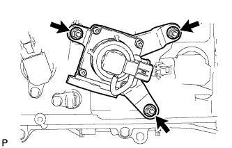
Remove the 3 nuts and emission control valve set.
-
-
REMOVE NO. 2 EMISSION CONTROL VALVE SET (w/ Secondary Air Injection System)
-
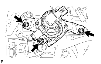
Remove the 3 nuts and No. 2 emission control valve set.
-
-
REMOVE IGNITION COIL ASSEMBLY
-
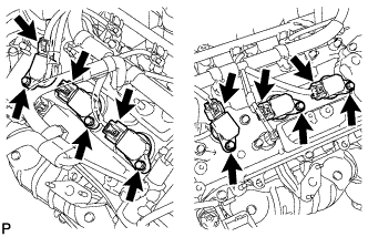
Disconnect the 6 ignition coil connectors.
-
Remove the 6 bolts and 6 ignition coils.
-
-
REMOVE ENGINE OIL LEVEL DIPSTICK GUIDE
-
Remove the dipstick.
-
Remove the bolt and dipstick guide.
-
Remove the O-ring from the dipstick guide.
-
-
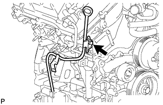
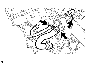
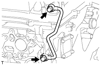
REMOVE WATER BY-PASS PIPE SUB-ASSEMBLY (w/ Oil Cooler)
-
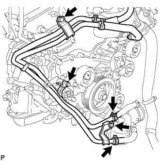
Disconnect the 2 hoses.
-
Remove the 3 bolts and water by-pass pipe.
-
-
REMOVE WATER INLET HOUSING
-
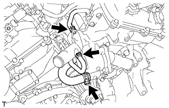
Disconnect the 3 water by-pass hoses.
-
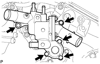
Remove the 5 bolts and water inlet housing.
-
Remove the O-ring and gasket from the water outlet pipe and water pump.
-
Remove the 3 water by-pass hoses.
-
-
REMOVE NO. 1 IDLER PULLEY SUB-ASSEMBLY
-
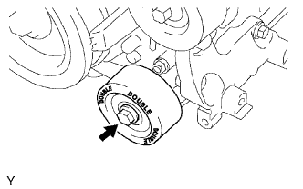
Remove the bolt and No. 1 idler pulley.
-
-
REMOVE NO. 2 IDLER PULLEY SUB-ASSEMBLY
-
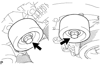
for Cover Separate Type:
Remove the 2 bolts, 2 idler pulley cover plates, 2 No. 2 idler pulleys and 2 No. 2 idler pulley cover plates.
-
for Cover Integrated Type:
Remove the 2 bolts and 2 No. 2 idler pulleys.
-
-
REMOVE V-RIBBED BELT TENSIONER ASSEMBLY
-
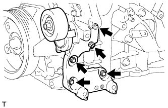
Remove the 5 bolts and V-ribbed belt tensioner.
-
-
REMOVE OIL FILTER BRACKET
-
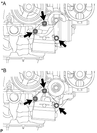
Text in Illustration *A w/ Oil Cooler *B w/o Oil Cooler Remove the 2 nuts, bolt, oil filter bracket and gasket.
-
-
REMOVE CRANKSHAFT PULLEY
-
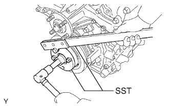
Using SST, hold the crankshaft pulley and loosen the pulley bolt. Continue to loosen the bolt until only 2 or 3 threads are screwed into the crankshaft.
- SST
- 09213-54015 ( 91651-60855 )
- 09330-00021
-
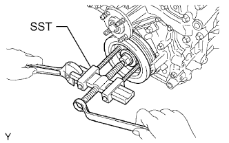
Using the pulley set bolt and SST, remove the crankshaft pulley and pulley bolt.
- SST
- 09950-50013 ( 09951-05010, 09952-05010, 09953-05020, 09954-05031 )
-
-
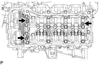
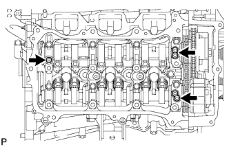
REMOVE NO. 1 OIL PIPE
-
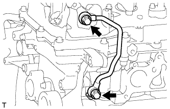
Remove the 2 oil pipe unions, oil control valve filter LH, 3 gaskets and No. 1 oil pipe.
Note
Do not touch the mesh when removing the oil control valve filter.
-
-
REMOVE NO. 2 OIL PIPE
-
Remove the 2 oil pipe unions, oil control valve filter RH, 3 gaskets and No. 2 oil pipe.
Note
Do not touch the mesh when removing the oil control valve filter.
-
-
REMOVE REAR CYLINDER HEAD COVER
-
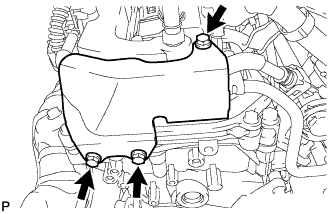
Remove the 3 bolts and cover.
-
-
DISCONNECT FUEL PIPE SUB-ASSEMBLY
-
Remove the 2 bolts and disconnect the fuel pipe.
-
-
REMOVE CYLINDER HEAD COVER SUB-ASSEMBLY LH
-
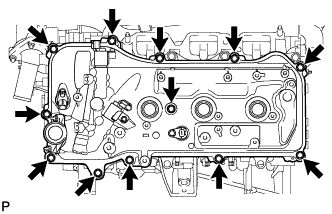
Remove the 12 bolts, seal washer, cylinder head cover and gasket.
Tech Tips
Make sure the removed parts are returned to the same places they were removed from.
-
Remove the 3 gaskets.
-
-
REMOVE CYLINDER HEAD COVER SUB-ASSEMBLY
-
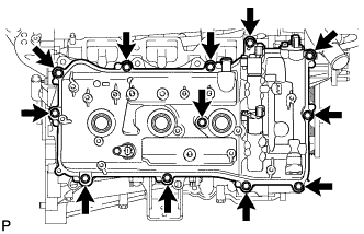
Remove the 12 bolts, seal washer, cylinder head cover and gasket.
Tech Tips
Make sure the removed parts are returned to the same places they were removed from.
-
Remove the 3 gaskets.
-
-
REMOVE NO. 2 OIL PAN SUB-ASSEMBLY
-
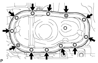
Remove the 10 bolts and 2 nuts.
Tech Tips
Make sure the removed parts are returned to the same places they were removed from.
-
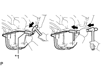
Text in Illustration *1 Oil Pan Seal Cutter Insert the blade of an oil pan seal cutter between the oil pans. Cut through the applied sealer and remove the No. 2 oil pan.
Note
Be careful not to damage the contact surfaces of the oil pans.
-
-
REMOVE OIL STRAINER SUB-ASSEMBLY
-
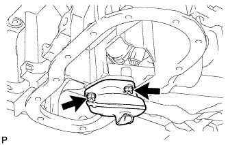
Remove the 2 nuts, oil strainer and gasket.
-
-
REMOVE OIL PAN SUB-ASSEMBLY
-
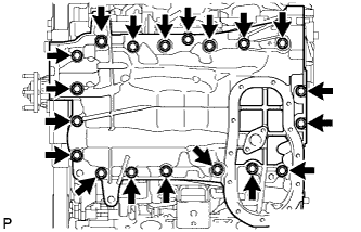
Remove the 17 bolts and 2 nuts.
Tech Tips
Make sure the removed parts are returned to the same places they were removed from.
-
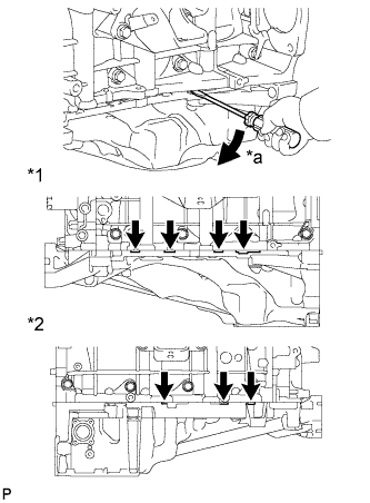
Text in Illustration *1 LH Side *2 RH Side *a Pry Using a screwdriver, remove the oil pan by prying between the oil pan and cylinder block as shown in the illustration.
Tech Tips
Tape the screwdriver tip before use.
Note
Be careful not to damage the contact surfaces of the cylinder block and oil pan.
-
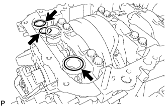
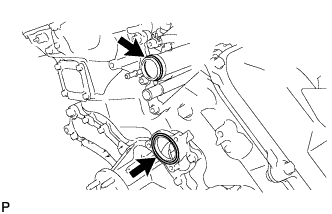
Remove the 3 O-rings from the timing chain cover.
-
-
REMOVE TIMING CHAIN COVER SUB-ASSEMBLY
-
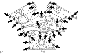
Remove the 26 bolts and the 2 nuts.
-
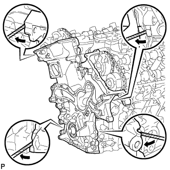
Remove the timing chain cover by prying between the timing chain cover and cylinder head or cylinder block with a screwdriver.
Tech Tips
Tape the screwdriver tip before use.
Note
Be careful not to damage the contact surfaces of the timing chain cover, cylinder block and cylinder head.
-
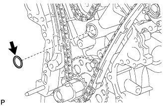
Remove the oil pump gasket from the cylinder block.
-
-
REMOVE FRONT CRANKSHAFT OIL SEAL
-
Using a screwdriver and wooden block, pry out the oil seal.
Tech Tips
Tape the screwdriver tip before use.
Note
Do not damage the surface of the oil seal press fit hole.
-