INTAKE SYSTEM (w/o DPF) ON-VEHICLE INSPECTION

-
INSPECT INTAKE SYSTEM
-
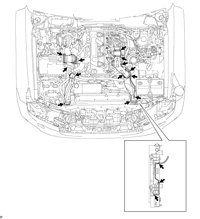
Check that there is no air suction or leaks at the points shown in the illustration.
-
For engine room area:
-
For engine area:
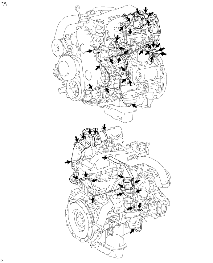
Text in Illustration *A w/o EGR System - - 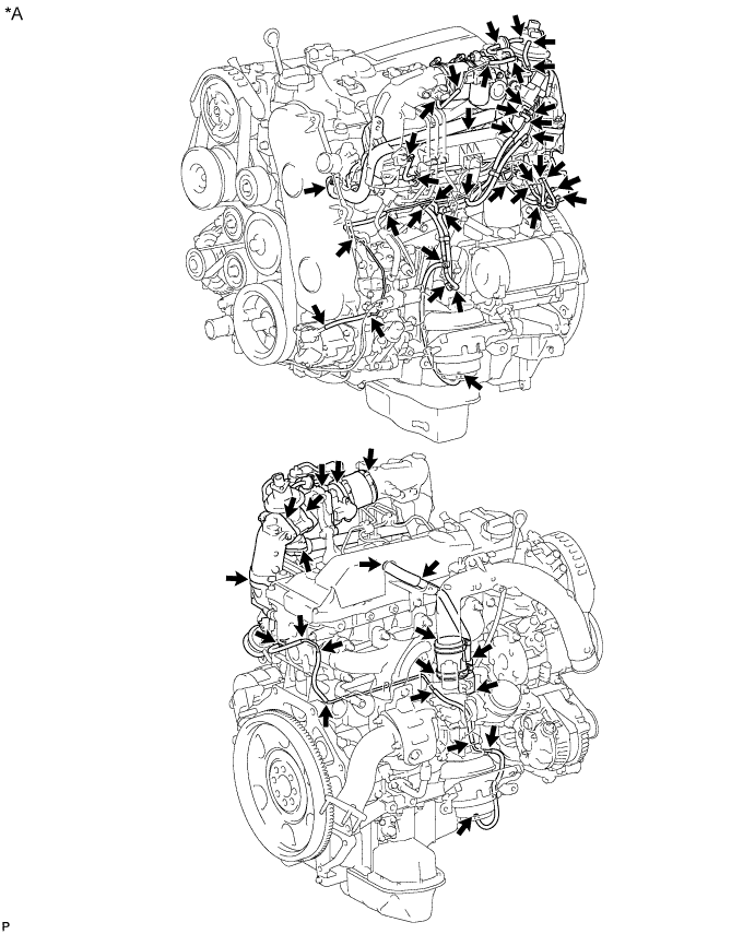
Text in Illustration *A w/ EGR System without EGR Cooler - - 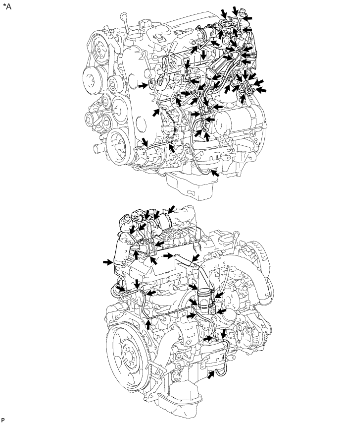
Text in Illustration *A w/ EGR System with EGR Cooler - - -
Layout of hoses for vacuum switching valves:
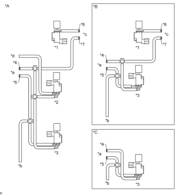
Text in Illustration *A w/ EGR System with EGR Cooler *B w/ EGR System without EGR Cooler *C w/o EGR System - - *1 Vacuum Switching Valve (for EGR Cut) *2 Vacuum Switching Valve (for EGR By-pass Valve) *3 Vacuum Switching Valve (for Engine Mounting) *4 Blue Paint *5 White Paint *6 Pink Paint *7 Yellow Paint - - *a to No. 2 Vacuum Transmitting Pipe *b to Front Engine Mounting Insulator LH *c to Vacuum Regulating Valve *d to EGR By-pass Valve
-
-
-
CHECK INTAKE AIR CONTROL SYSTEM
-
Check for leakage or clogging between the air cleaner housing and turbocharger inlet and between the turbocharger outlet and cylinder head.
Condition Operation Clogged air cleaner Clean or replace element Hoses collapsed or deformed Repair or replace Leakage from connections Check each connection and repair Cracks in components Check and repair or replace
-
-
CHECK EXHAUST SYSTEM
-
Check for leakage or clogging between the cylinder head and turbocharger inlet and between the turbocharger outlet and exhaust pipe.
Condition Operation Deformed components Repair or replace Foreign material in passages Remove Leakage from components Repair or replace Cracks in components Check and repair or replace
-
-
CHECK BOOST PRESSURE
-
Connect the intelligent tester to the DLC3.
-
Start the engine and turn the tester on.
-
Warm up the engine.
Tech Tips
Be sure to perform the inspection when the engine coolant temperature is between 75 and 90°C (167 and 194°F).
-
Enter the following menus: Powertrain / Engine and ECT / Data List / All Data.
-
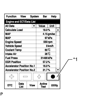
Text in Illustration *1 Snapshot Record Button Take a snapshot of the Data List items with the intelligent tester as shown in the illustration.
Tech Tips
-
Graphs can be displayed by transferring the stored snapshot data from the tester to a PC. Intelligent Viewer must be installed on the PC.
-
The condition of the turbocharger can be determined by fully depressing the accelerator pedal while driving at 15 km/h (9 mph) in 2nd gear to accelerate the vehicle (obey all laws and regulations and pay attention to driving conditions while driving the vehicle), and then comparing MAP with Target Booster Pressure at an engine speed of 3000 rpm.
-
-
Compare MAP with Target Booster Pressure.
Standard MAP is within 20 kPa of Target Booster Pressure when accelerating with accelerator pedal fully depressed. Tech Tips
-
The inspection above is only for vehicles equipped with a manual transmission.
-
If the above driving inspection using the intelligent tester cannot be performed (e.g. due to road conditions), or if the vehicle is equipped with an automatic transmission, perform the following inspection.
-
Warm up the engine.
Tech Tips
Be sure to perform the inspection when the engine coolant temperature is between 75 and 90°C (167 and 194°F).
-
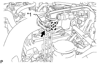
Text in Illustration *1 Turbo Pressure Sensor Detach the clamp and disconnect the vacuum hose from the manifold absolute pressure sensor.
-
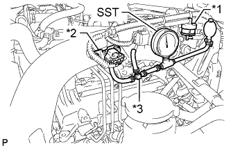
Text in Illustration *1 Gas Filter *2 Manifold Absolute Pressure Sensor *3 3-way Connector Using a 3-way connector, connect SST (turbocharger pressure gauge) between the manifold absolute pressure sensor and gas filter.
- SST
- 09992-00242
-
for Manual Transmission:
While depressing the clutch pedal, fully depress the accelerator pedal. Measure the boost pressure at maximum engine speed (4450 to 4750 rpm).
Standard pressure 5 to 20 kPa (0.05 to 0.2 kgf/cm2, 0.7 to 2.9 psi) -
for Automatic Transmission:
Move the shift lever to P or N, and then fully depress the accelerator pedal. Measure the boost pressure at maximum engine speed (4450 to 4750 rpm).
Standard pressure 5 to 20 kPa (0.05 to 0.2 kgf/cm2, 0.7 to 2.9 psi) If the pressure is below the standard, the following problems may be present.
-
The intake system or exhaust system has leakage or blockage.
-
The turbocharger sub-assembly is malfunctioning.
-
The electric EGR control valve does not close.
-
The diesel throttle body does not open.
-
The vacuum hose connected to the manifold absolute pressure sensor is cracked or disconnected.
-
The mass air flow meter sub-assembly is malfunctioning.
-
A fuel injector assembly is malfunctioning.
If the pressure is higher than the standard, check the turbocharger.
-
-
-
Chart showing the suspected trouble areas when the pressure is below the standard.
Tech Tips
-
○: If a problem listed in the leftmost column of the chart exists, or if the part in the leftmost column of the chart has a malfunction, the value of the Data List item in the uppermost row of the chart will meet the conditions shown in the row labeled "Value which represents a malfunction".
-
The values in the chart are applicable when the engine coolant temperature is between 75 and 90°C (167 and 194°F).
-
The values in the chart are for vehicles equipped with a manual transmission. For vehicles with an automatic transmission, use these values as a reference only as they may differ from the actual values.
-
The values in the chart are valid in an area with an atmospheric pressure higher than 95 kPa (1.0 kgf/cm2, 14 psi). Standard atmospheric pressure is 101 kPa (1.0 kgf/cm2, 15 psi). Atmospheric pressure decreases by 1 kPa (0.01 kgf/cm2, 0.1 psi) for every 100 m increase in altitude, and is also affected by the current weather conditions.
-
When the altitude increases, atmospheric pressure and MAP decrease.
Item MAP
(Absolute pressure inside intake manifold)
MAF
(Intake air flow rate)
Accel Position Actual Throttle Position Actual EGR Valve Position EGR Close Lrn. Status
(EGR valve fully closed position learning status)
Fuel Pressure Injection Feedback Val #1 (to #4) Values taken from an actual normal vehicle
*1
- 150 g/sec. 100% 0% 0% OK - -3 to +3 mm3/st
Values which represent a malfunction
*1
MAP is below Target Booster Pressure by 25 kPa or more MAF is less than 90 g/sec. Accel Position is less than 90% Actual Throttle Position is not within 5% of Target Throttle Position Actual EGR Valve Position is not within 5% of Target EGR Valve Position NG
(Determined after performing learning)
Fuel Pressure is below Target Common Rail Pressure by 10 MPa or more (Check while condition steady) Outside of above range Turbocharger ○ ○ - - - - - - EGR valve does not close or has problem with movement ○ ○ - - ○
(Problem with EGR valve movement)
*2
○
(EGR valve does not close)
*2
- - Problem with diesel throttle movement ○
(Intake airflow decreases)
○ - ○ - - - - Accelerator pedal cannot be fully depressed or problem with accelerator pedal position sensor exists - ○ ○ - - - - - Intake air system leakage or blockage ○ ○ - - - - - - Exhaust gas leakage before turbocharger or blockage ○ ○ - - - - - - Manifold absolute pressure sensor ○ ○ - - - - - - Manifold absolute pressure sensor hose is disconnected ○ ○ - - - - - - Mass air flow meter sub-assembly - ○ - - - - - - Fuel system (injector, supply pump or common rail) ○ ○ - - - - ○
(Fuel injector leakage, decrease in pressure discharge valve relief pressure or valve is stuck)
○
*3
Tech Tips
-
*1: These values are measured when the transmission is in 2nd gear, the accelerator pedal is fully depressed, the vehicle is accelerating, and the engine speed is 3000 rpm.
-
*2: DTC P0400 may be stored at this time. If the actual EGR valve position follows the target EGR valve position slowly, a feeling of hesitation may occur.
-
*3: If Injection Feedback Val # of a cylinder is not within -3 to +3 mm3/st, the corresponding cylinder has a malfunction (injector or compression). However, in some cases the cylinder may be malfunctioning even if the value is within -3 to +3 mm3/st.
-
-
-
CHECK MOTOR FOR TURBOCHARGER CONTROL OPERATION
-
Remove the No. 1 turbo insulator and No. 1 exhaust manifold heat insulator Click here.
-
Check the stroke.
Note
Make sure the DC motor connectors are properly connected.
-
Turn the ignition switch from ON to off.
-
Check the DC motor operation. Check that the motor rod stroke is as shown in A to D in the illustration below.
-
After the DC motor operates, visually check that the vane activation link contacts the fully closed stopper.
OK When ignition switch is turned OFF, operation link moves as shown in A through D in illustration below. Operation link and motor rod move smoothly when moving from position shown in A to that shown in B, and from position shown in B to that shown in C. Note
Never loosen or tighten the lock nut of the fully closed stopper.
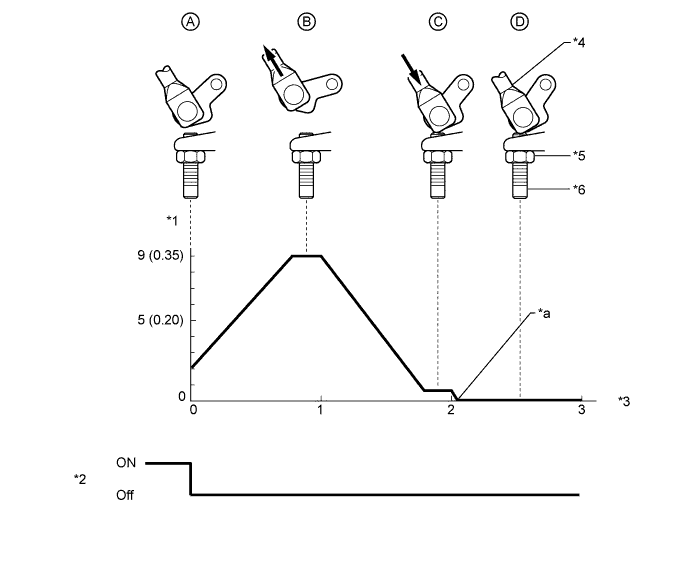
Text in Illustration *1 Motor Rod Stroke (mm (in.)) *2 Ignition Switch *3 Ignition Switch Off Time (sec.) *4 Motor Rod *5 Lock Nut *6 Fully Closed Stopper *a Fully Closed Stopper Contact - - If the result is not as specified, check the ECM Click here.
-
-