EXHAUST MANIFOLD INSTALLATION

-
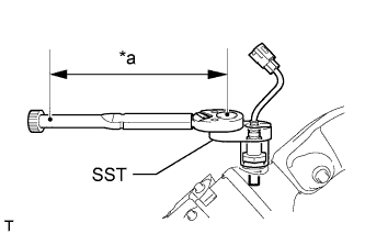
INSTALL AIR FUEL RATIO SENSOR (for Bank 2 Sensor 1)
-
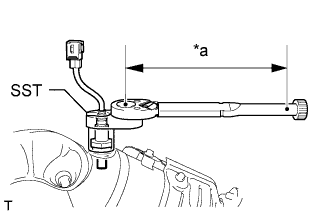
Text in Illustration *a Fulcrum Length Using SST, install the sensor.
- SST
- 09224-00010
- Torque:
- without SST
- 44 N*m { 449 kgf*cm, 32 ft.*lbf }
- with SST
- 40 N*m { 408 kgf*cm, 30 ft.*lbf }
Tech Tips
-
Use a torque wrench with a fulcrum length of 30 cm (11.8 in.). When using a torque wrench with a fulcrum length that is not 30 cm (11.8 in.), calculate the torque specification for the torque wrench and SST based on the "without SST" torque specification Click here.
-
Make sure SST and the wrench are connected in a straight line.
-
-
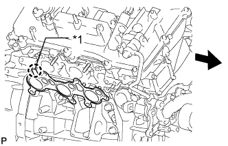
INSTALL EXHAUST MANIFOLD SUB-ASSEMBLY LH
-
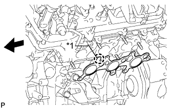
Text in Illustration *1 Protrusion 
Front Install a new gasket to the cylinder head.
Note
Be careful of the installation direction.
-
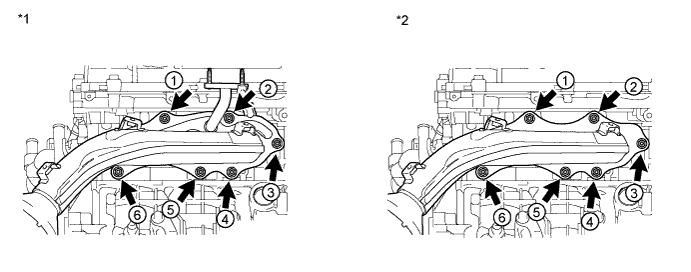
Temporarily install the manifold with 6 new nuts.
-
Tighten the 6 nuts in the sequence shown in the illustration.
- Torque:
- 21 N*m { 214 kgf*cm, 15 ft.*lbf }
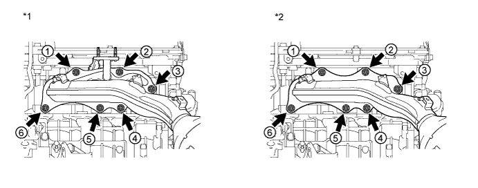
Text in Illustration *1 w/ Secondary Air Injection System *2 w/o Secondary Air Injection System -
Connect the air fuel ratio sensor connector.
-
-
INSTALL NO. 2 EXHAUST MANIFOLD HEAT INSULATOR
-
Install the heat insulator with the 3 bolts.
- Torque:
- 13 N*m { 133 kgf*cm, 10 ft.*lbf }
-
-
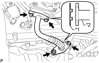
INSTALL NO. 2 AIR TUBE (w/ Secondary Air Injection System)
-
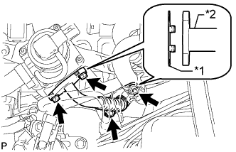
Text in Illustration *1 New Gasket *2 No. 2 Air Tube Install 2 new gaskets to the No. 2 air tube.
-
Install the No. 2 air tube with the 2 bolts and 2 nuts.
- Torque:
- 10 N*m { 102 kgf*cm, 7 ft.*lbf }
-
-
INSTALL MANIFOLD STAY
-
Install the manifold stay with the 3 bolts.
- Torque:
- 40 N*m { 408 kgf*cm, 30 ft.*lbf }
-
-
INSTALL AIR FUEL RATIO SENSOR (for Bank 1 Sensor 1)
-
Text in Illustration *a Fulcrum Length Using SST, install the sensor.
- SST
- 09224-00010
- Torque:
- without SST
- 44 N*m { 449 kgf*cm, 32 ft.*lbf }
- with SST
- 40 N*m { 408 kgf*cm, 30 ft.*lbf }
Tech Tips
-
Use a torque wrench with a fulcrum length of 30 cm (11.8 in.). When using a torque wrench with a fulcrum length that is not 30 cm (11.8 in.), calculate the torque specification for the torque wrench and SST based on the "without SST" torque specification Click here.
-
Make sure SST and the wrench are connected in a straight line.
-
-
INSTALL EXHAUST MANIFOLD SUB-ASSEMBLY RH
-
Text in Illustration *1 Protrusion Front Install a new gasket to the cylinder head.
Note
Be careful of the installation direction.
-
Temporarily install the manifold with 6 new nuts.
-
Tighten the 6 nuts in the sequence shown in the illustration.
- Torque:
- 21 N*m { 214 kgf*cm, 15 ft.*lbf }
Text in Illustration *1 w/ Secondary Air Injection System *2 w/o Secondary Air Injection System -
Connect the air fuel ratio sensor connector.
-
-
INSTALL NO. 1 EXHAUST MANIFOLD HEAT INSULATOR
-
Install the heat insulator with the 3 bolts.
- Torque:
- 13 N*m { 133 kgf*cm, 10 ft.*lbf }
-
-
CONNECT NO. 2 STEERING INTERMEDIATE SHAFT SUB-ASSEMBLY (for RHD)
-
for Manual Tilt and Manual Telescopic Steering Column:
Connect the No. 2 steering intermediate shaft Click here.
-
for Power Tilt and Power Telescopic Steering Column:
Connect the No. 2 steering intermediate shaft Click here.
-
-
INSTALL AIR TUBE (w/ Secondary Air Injection System)
-
Text in Illustration *1 New Gasket *2 Air Tube Install 2 new gaskets to the air tube.
-
Install the air tube with the 2 bolts and 2 nuts.
- Torque:
- 10 N*m { 102 kgf*cm, 7 in.*lbf }
-
-
INSTALL NO. 2 MANIFOLD STAY
-
Install the manifold stay with the 3 bolts.
- Torque:
- 40 N*m { 408 kgf*cm, 30 ft.*lbf }
-
-
INSTALL FRONT EXHAUST PIPE ASSEMBLY
-
Install the front exhaust pipe Click here.
-
-
INSTALL AIR CLEANER CASE SUB-ASSEMBLY
-
Install the air cleaner case with the 3 bolts.
- Torque:
- 12 N*m { 122 kgf*cm, 9 ft.*lbf }
-
Attach the wire harness clamp.
-
Install the air cleaner filter element.
-
-
INSTALL AIR CLEANER CAP AND HOSE
-
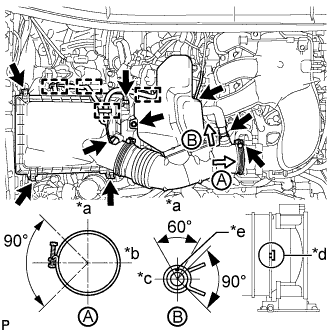
Text in Illustration *a Top *b Front *c RH *d Align cutout portion of hose with protrusion of throttle *e Paint Mark Install the air cleaner cap and hose.
-
Install the air cleaner cap and hose with the bolt and fasten the 4 hook clamps.
- Torque:
- 5.0 N*m { 51 kgf*cm, 44 in.*lbf }
-
Tighten the clamp.
- Torque:
- 5.0 N*m { 51 kgf*cm, 44 in.*lbf }
-
Attach the 4 clamps and connect the ventilation hose, vacuum hose and mass air flow meter connector.
Tech Tips
The direction of the hose clamp is indicated in the illustration.
-
-
-
INSTALL V-BANK COVER
-
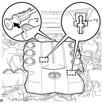
Text in Illustration *1 Pin *2 Hook Attach the 2 V-bank cover hooks to the bracket. Then align the 2 V-bank cover grommets with the 2 pins and press down on the V-bank cover to attach the pins.
-
-
INSTALL UPPER RADIATOR SUPPORT SEAL
-
Install the upper radiator support seal with the 13 clips.
-
-
INSPECT FOR EXHAUST GAS LEAK
-
If gas is leaking, tighten the areas necessary to stop the leak. Replace damaged parts as necessary.
-
-
INSTALL FRONT FENDER APRON SEAL LH
-
w/ KDSS:
Install the apron seal with the 7 clips.
-
w/o KDSS:
Install the apron seal with the 4 clips.
-
-
INSTALL FRONT FENDER APRON SEAL RH
-
Install the apron seal with the 5 clips.
-
-
INSTALL FRONT NO. 1 FENDER APRON TO FRAME SEAL LH
-
Install the frame seal with the 5 clips.
-
-
INSTALL FRONT NO. 1 FENDER APRON TO FRAME SEAL RH
-
Install the frame seal with the 5 clips.
-