INTAKE MANIFOLD INSTALLATION

-
INSTALL INTAKE MANIFOLD
-
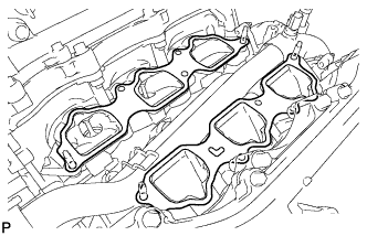
Set a new gasket on each cylinder head.
Note
-
Align the port holes of the gasket and cylinder head.
-
Be careful of the installation direction.
-
-
Set the intake manifold on the cylinder heads.
-
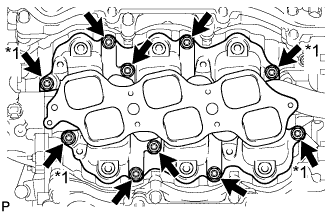
Text in Illustration *1 Nut Install and uniformly tighten the 6 bolts and 4 nuts in several passes.
- Torque:
- 21 N*m { 214 kgf*cm, 15 ft.*lbf }
Tech Tips
Tighten the inner installation bolts of the intake manifold before tightening the outer bolts.
-
-
INSTALL FUEL DELIVERY PIPE SUB-ASSEMBLY
-
Place the fuel delivery pipe together with the 6 fuel injectors on the intake manifold.
-
Temporarily install the 6 bolts, which are used to hold the fuel delivery pipe in place, to the intake manifold.
-
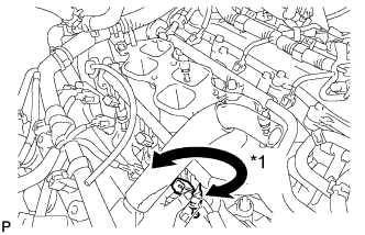
Text in Illustration *1 Turn Check that the fuel injectors rotate smoothly.
If the fuel injectors do not rotate smoothly, replace the O-ring of any injector that does not rotate smoothly.
-
Position the fuel injectors with the connectors facing outward.
-
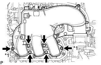
Tighten the 6 bolts.
- Torque:
- 21 N*m { 214 kgf*cm, 15 ft.*lbf }
-
Connect the 6 fuel injector connectors.
-
-
INSTALL INTAKE AIR SURGE TANK
-
Install a new gasket to the intake air surge tank.
-
Text in Illustration *1 Nut Install the intake air surge tank with the 4 bolts and 2 nuts in the order shown in the illustration.
- Torque:
- 28 N*m { 286 kgf*cm, 21 ft.*lbf }
-
Install the No. 1 surge tank stay with the 2 bolts.
- Torque:
- 21 N*m { 214 kgf*cm, 15 ft.*lbf }
-
Attach the wire harness clamp.
-
Install the No. 2 surge tank stay with the 2 bolts.
- Torque:
- 21 N*m { 214 kgf*cm, 15 ft.*lbf }
-
Install the throttle body bracket with the 2 bolts.
- Torque:
- 21 N*m { 214 kgf*cm, 15 ft.*lbf }
-
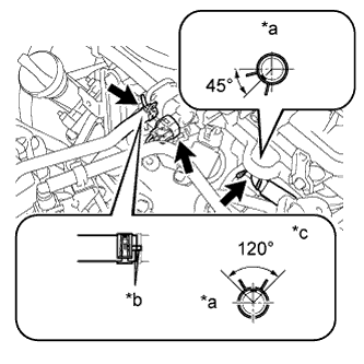
Text in Illustration *a Front *b Matchmark *c Top Connect the No. 1 ventilation hose.
-
Connect the No. 1 vacuum switching valve connector.
-
Connect the No.1 fuel feed hose.
Tech Tips
Connect the hose so that the direction of the hose clamp is as indicated in the illustration.
-
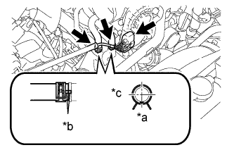
Text in Illustration *a Front *b Matchmark *c RH Connect the throttle body connector.
-
Connect the No. 4 water by-pass hose.
-
Connect the No. 5 water by-pass hose.
Tech Tips
Connect the hose so that the direction of the hose clamp is as indicated in the illustration.
-
Connect the 2 heater hose clamps.
-
-
INSTALL AIR TUBE ASSEMBLY (w/ Secondary Air Injection System)
-
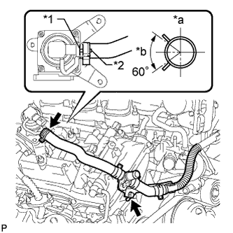
Text in Illustration *1 Rib *2 Paint Mark *a RH Side *b Upper for Bank 1 Side:
Align the paint mark with the projection and connect the air tube assembly to the emission control valve set.
Tech Tips
Make sure the direction of the hose clamp is as shown in the illustration.
-
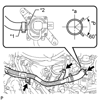
Text in Illustration *1 Paint Mark *2 Rib *a Upper *b LH Side for Bank 2 Side:
Align the paint mark with the projection and connect the air tube assembly to the No. 2 emission control valve set.
Tech Tips
Make sure the direction of the hose clamp is as shown in the illustration.
-
Install the 3 bolts.
- Torque:
- 10 N*m { 102 kgf*cm, 7 ft.*lbf }
-
-
INSTALL NO. 1 AIR CLEANER HOSE
-
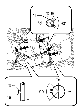
Text in Illustration *1 Paint mark *a Protrusion *b Groove *c Top *d RH *e Front Install the air cleaner hose with the 2 clamps.
- Torque:
- 5.0 N*m { 51 kgf*cm, 44 in.*lbf }
-
Install the bolt.
- Torque:
- 5.0 N*m { 51 kgf*cm, 44 in.*lbf }
-
Connect the vacuum hose and ventilation hose.
Tech Tips
The direction of the hose clamp is indicated in the illustration.
-
Attach the wire harness clamp.
-
-
CONNECT CABLE TO NEGATIVE BATTERY TERMINAL
Note
When disconnecting the cable, some systems need to be initialized after the cable is reconnected Click here.
-
ADD ENGINE COOLANT
-
Tighten the cylinder block drain cock plug.
- Torque:
- 13 N*m { 130 kgf*cm, 9 ft.*lbf }
-
Tighten the radiator drain cock plug by hand.
-
Add engine coolant.
Standard Capacity Item Specified Condition for Automatic Transmission w/o Warmer w/o Rear Heater 10.5 liters (11.1 US qts, 9.2 Imp. qts) w/ Rear Heater 12.3 liters (13.0 US qts, 10.8 Imp. qts) w/ Warmer w/o Rear Heater 11.0 liters (11.6 US qts, 9.7 Imp. qts) w/ Rear Heater 12.8 liters (13.5 US qts, 11.3 Imp. qts) for Manual Transmission w/o Rear Heater 10.7 liters (11.3 US qts, 9.4 Imp. qts) w/ Rear Heater 12.5 liters (13.2 US qts, 11.0 Imp. qts) Note
Do not substitute plain water for engine coolant.
Tech Tips
-
TOYOTA vehicles are filled with TOYOTA SLLC at the factory. In order to avoid damage to the engine cooling system and other technical problems, only use TOYOTA SLLC or similar high quality ethylene glycol based non-silicate, non-amine, non-nitrite, non-borate coolant with long-life hybrid organic acid technology (coolant with long-life hybrid organic acid technology consists of a combination of low phosphates and organic acids).
-
Press the No. 1 and No. 2 radiator hoses several times by hand, and then check the coolant level. If the coolant level is low, add coolant.
-
-
Slowly pour coolant into the radiator reservoir until it reaches the F line.
-
Install the reservoir cap.
-
Install the radiator cap.*1
-
Start the engine and stop it immediately.*2
-
Allow approximately 10 seconds to pass. Then remove the radiator cap and check the coolant level. If the coolant level has decreased, add coolant.*3
-
Repeat steps *1, *2 and *3 until the coolant level does not decrease.
Tech Tips
Be sure to perform this step while the engine is cold, as air in the No. 1 radiator hose will flow into the radiator if the engine is warmed up and the thermostat opens.
-
Install the radiator cap.*4
-
Set the air conditioning as follows.*5
Item Condition Fan speed Any setting except off Temperature Toward WARM Air conditioning switch Off -
Start the engine, warm it up until the thermostat opens, and then continue to run the engine for several minutes to circulate the coolant.*6
CAUTION:
-
Wear protective gloves. Hot areas on the parts may injure your hands.
-
Be careful of the fan.
-
Be careful as the engine, radiator and radiator hoses are hot and can cause burns.
Note
-
Immediately after starting the engine, if the radiator reservoir does not have any coolant, perform the following: 1) stop the engine, 2) wait until the coolant has cooled down, and 3) add coolant until the coolant is filled to the F line.
-
Do not start the engine when there is no coolant in the radiator reservoir.
-
Pay attention to the needle of the engine coolant temperature receiver gauge. Make sure that the needle does not show an abnormally high temperature.
-
If there is not enough coolant, the engine may burn out or overheat.
Tech Tips
-
Press the No. 1 and No. 2 radiator hoses several times by hand to bleed air while warming up the engine.
-
The thermostat opening timing can be confirmed by pressing the No. 2 radiator hose by hand and checking when the engine coolant starts to flow inside the hose.
-
-
Stop the engine, wait until the engine coolant cools down to ambient temperature. Then remove the radiator cap and check the coolant level.*7
CAUTION:
Do not remove the radiator cap while the engine and radiator are still hot. Pressurized, hot engine coolant and steam may be released and cause serious burns.
-
If the coolant level has decreased, add coolant and warm up the engine until the thermostat opens.*8
-
If the coolant level has not decreased, check that the coolant level in the radiator reservoir is at the F line.
If the coolant level is below the F line, repeat steps *4 through *8.
If the coolant level is above the F line, drain coolant until the coolant level reaches the F line.
-
-
INSPECT FOR COOLANT LEAK
CAUTION:
To avoid being burned, do not remove the radiator reservoir cap while the engine and radiator are still hot. Thermal expansion may cause hot engine coolant and steam to blow out from the radiator.
-
Fill the radiator with engine coolant, and then attach a radiator cap tester.
-
Warm up the engine.
-
Using the radiator cap tester, increase the pressure inside the radiator to 123 kPa (1.3 kgf/cm2, 18 psi), and then check that the pressure does not drop.
If the pressure drops, check the hoses, radiator and water pump for leakage. If there are no signs or traces of external engine coolant leakage, check the heater core, cylinder block and head.
-
-
INSPECT FOR FUEL LEAK
-
Make sure that there are no fuel leaks after performing maintenance on the fuel system.
-
Connect the intelligent tester to the DLC3.
-
Turn the ignition switch to ON and turn the intelligent tester on.
Note
Do not start the engine.
-
Enter the following menus: Powertrain / Engine and ECT / Active Test / Control the Fuel Pump / Speed.
-
Check that there are no leaks from the fuel system.
If there are fuel leaks, repair or replace parts as necessary.
-
Turn the ignition switch off.
-
Disconnect the intelligent tester from the DLC3.
-
-
-
INSTALL V-BANK COVER
-
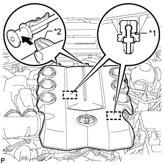
Text in Illustration *1 Pin *2 Hook Attach the 2 V-bank cover hooks to the bracket. Then align the 2 V-bank cover grommets with the 2 pins and press down on the V-bank cover to attach the pins.
-
-
INSTALL NO. 1 ENGINE UNDER COVER SUB-ASSEMBLY
-
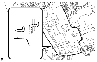
Hook the engine under cover to the vehicle body as shown in the illustration.
-
Install the 4 bolts.
- Torque:
- 29 N*m { 296 kgf*cm, 21 ft.*lbf }
-
-
INSTALL FRONT BUMPER COVER LOWER
-
Install the front bumper cover lower with the 5 bolts and clip.
- Torque:
- 8.0 N*m { 82 kgf*cm, 71 in.*lbf }
-