INTAKE MANIFOLD REMOVAL

-
DISCHARGE FUEL SYSTEM PRESSURE
-
Discharge the fuel system pressure Click here.
-
-
DISCONNECT CABLE FROM NEGATIVE BATTERY TERMINAL
CAUTION:
Wait at least 90 seconds after disconnecting the cable from the negative (-) battery terminal to disable the SRS system.
Note
-
After turning the ignition switch off, waiting time may be required before disconnecting the cable from the battery terminal. Therefore, make sure to read the disconnecting the cable from the battery terminal notice before proceeding with work Click here.
-
When disconnecting the cable, some systems need to be initialized after the cable is reconnected Click here.
-
-
REMOVE FRONT BUMPER COVER LOWER
-
Remove the clip, 5 bolts and front bumper cover lower.
-
-
REMOVE NO. 1 ENGINE UNDER COVER SUB-ASSEMBLY
-
Remove the 4 bolts.
-
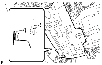
Unhook the engine under cover from the vehicle body as shown in the illustration.
-
-
DRAIN ENGINE COOLANT
CAUTION:
Do not remove the radiator cap while the engine and radiator are still hot. Pressurized, hot engine coolant and steam may be released and cause serious burns.

Text in Illustration *1 Reservoir Cap *2 Radiator Cap *3 Radiator Drain Cock Plug *4 Cylinder Block Drain Cock Plug
-
Loosen the radiator drain cock plug.
-
Remove the radiator cap and drain the coolant.
Tech Tips
Collect the coolant in a container and dispose of it according to the regulations in your area.
-
Loosen the cylinder block drain cock plug and drain the coolant from the engine.
-
-
REMOVE V-BANK COVER
-
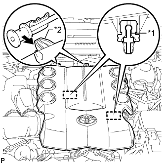
Text in Illustration *1 Pin *2 Hook Raise the front of the V-bank cover to detach the 2 pins. Then remove the 2 V-bank cover hooks from the bracket, and remove the V-bank cover.
-
-
REMOVE NO. 1 AIR CLEANER HOSE
-
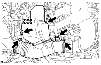
Disconnect the ventilation hose and vacuum hose.
-
Detach the wire harness clamp.
-
Remove the bolt and loosen the 2 hose clamps.
-
Remove the No. 1 air cleaner hose.
-
-
REMOVE AIR TUBE ASSEMBLY (w/ Secondary Air Injection System)
-
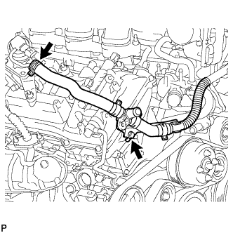
for Bank 1 Side:
Remove the bolt and disconnect the air tube assembly from the emission control valve set.
-
for Bank 2 Side:
Remove the 2 bolts and disconnect the air tube assembly from the No. 2 emission control valve set.
-
-
REMOVE INTAKE AIR SURGE TANK
-
Disconnect the throttle body connector.
-
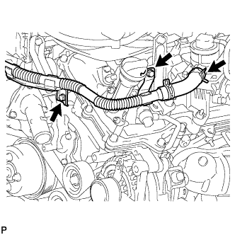
Disconnect the No. 4 water by-pass hose.
-
Disconnect the No. 5 water by-pass hose.
-
Disconnect the No. 1 fuel vapor feed hose.
-
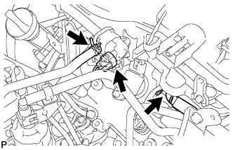
Disconnect the No. 1 vacuum switching valve connector.
-
Disconnect the No. 1 ventilation hose.
-
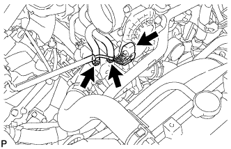
Detach the 2 heater hose clamps.
-
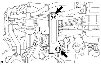
Remove the 2 bolts and throttle body bracket.
-
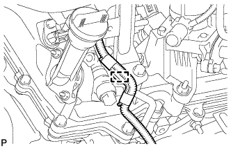
Using a clip remover, detach the wire harness clamp.
-
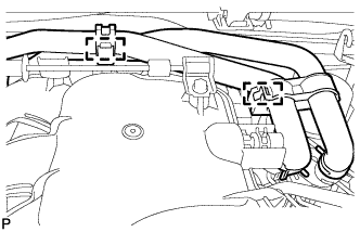
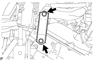
Remove the 2 bolts and No. 1 surge tank stay.
-
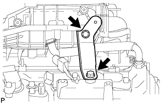
Remove the 2 bolts and No. 2 surge tank stay.
-
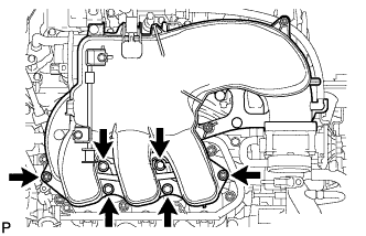
Remove the 2 nuts, 4 bolts and intake air surge tank.
-
Remove the gasket.
-
-
REMOVE FUEL DELIVERY PIPE SUB-ASSEMBLY
-
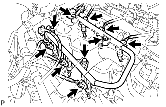
Disconnect the 6 fuel injector connectors.
-
Remove the 4 bolts and fuel delivery pipe together with the 6 fuel injectors.
Note
Be careful not to drop the injectors when removing the fuel delivery pipe.
-
-
REMOVE INTAKE MANIFOLD
-
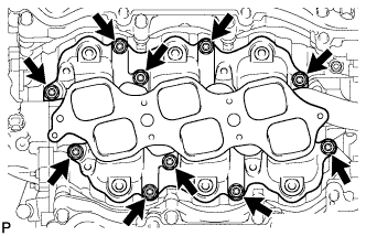
Remove the 4 nuts, 6 bolts and 2 gaskets.
-