EXHAUST MANIFOLD W/ TURBOCHARGER (w/ DPF) REMOVAL

-
DISCONNECT CABLE FROM NEGATIVE BATTERY TERMINAL
Note
-
After turning the engine switch off, waiting time may be required before disconnecting the cable from the battery terminal. Therefore, make sure to read the disconnecting the cable from the battery terminal notice before proceeding with work Click here.
-
When disconnecting the cable, some systems need to be initialized after the cable is reconnected Click here.
-
-
REMOVE FRONT EXHAUST PIPE ASSEMBLY
-
REMOVE FRONT BUMPER LOWER COVER
-
Remove the clip, 5 bolts and front bumper lower cover.
-
-
REMOVE NO. 1 ENGINE UNDER COVER
-
Remove the 4 bolts and No. 1 engine under cover.
-
-
DRAIN ENGINE COOLANT
CAUTION:
Do not remove the radiator reservoir cap while the engine and radiator are still hot. Pressurized, hot engine coolant and steam may be released and cause serious burns.
-
Loosen the radiator drain cock plug.
Tech Tips
Collect the coolant in a container and dispose of it according to the regulations in your area.
-
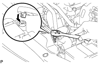
Drain the coolant by removing the reservoir cap and, using a wrench, remove the vent plug.
-
Loosen the cylinder block drain cock plug.
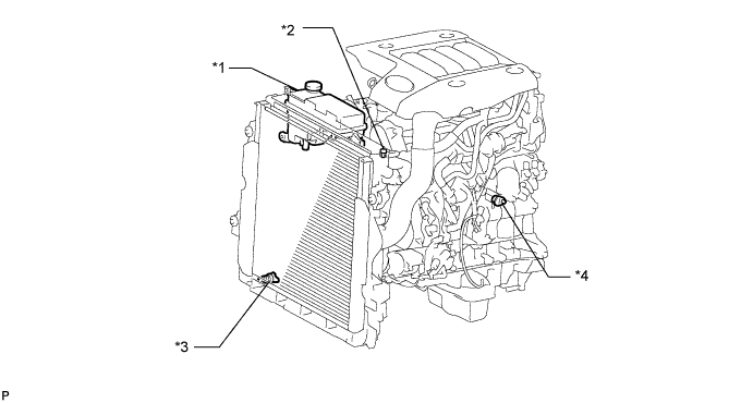
Text in Illustration *1 Radiator Reservoir *2 Vent Plug *3 Radiator Drain Cock Plug *4 Cylinder Block Drain Cock Plug
-
-
REMOVE FRONT FENDER APRON SEAL RH
-
Using a clip remover, remove the 5 clips and front fender apron seal RH.
-
-
REMOVE FRONT NO. 1 FENDER APRON TO FRAME SEAL RH
-
Using a clip remover, remove the 4 clips and front No. 1 fender apron to frame seal RH.
-
-
REMOVE UPPER RADIATOR SUPPORT SEAL
-
Remove the 13 clips and upper radiator support seal.
-
-
REMOVE FRONT HEATER BRACKET (for Cold Area Specification Vehicles)
-
Remove the 2 bolts and front heater bracket.
-
-
REMOVE FAN AND GENERATOR V BELT
-
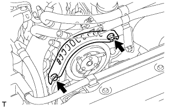
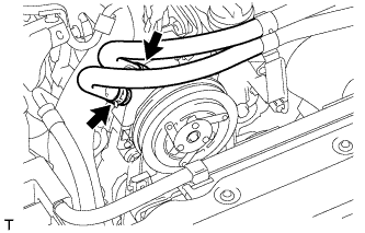
Using the pulley set bolt of the tensioner, rotate the tensioner pulley clockwise to loosen the belt tension. Then remove the V belt.
-
-
REMOVE NO. 1 AIR CLEANER HOSE
-
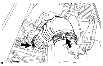
Loosen the 2 hose clamps and remove the No. 1 air cleaner hose.
-
-
REMOVE AIR CLEANER CAP SUB-ASSEMBLY
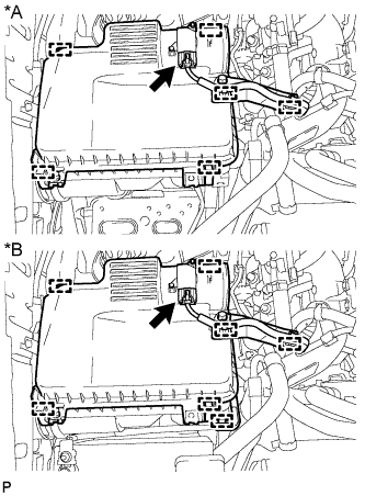
Text in Illustration *A except Cold Area Specification Vehicles *B for Cold Area Specification Vehicles
-
except Cold Area Specification Vehicles:
Detach the 2 clamps and disconnect the mass air flow meter connector.
-
for Cold Area Specification Vehicles:
Detach the 3 clamps and disconnect the mass air flow meter connector.
-
Detach the 4 clamps and remove the air cleaner cap sub-assembly.
-
-
REMOVE AIR CLEANER FILTER ELEMENT SUB-ASSEMBLY
-
REMOVE AIR CLEANER CASE SUB-ASSEMBLY
-
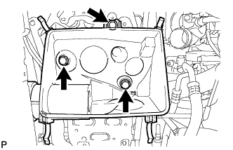
Remove the 3 bolts and air cleaner case sub-assembly.
-
-
DISCONNECT HEATER HOSE AND PIPE (w/ Rear Air Conditioning System)
-
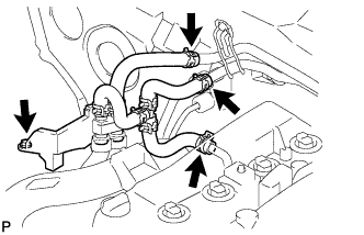
Slide the 3 clamps, disconnect the 3 heater hoses from the heater pipe.
-
Remove the bolt and disconnect the heater hose and pipe.
-
-
REMOVE HEATER HOSE (w/o Rear Air Conditioning System)
-
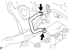
Slide the 2 clamps and remove the heater hose from the heater pipe.
-
-
REMOVE NO. 1 AIR HOSE
-
Loosen the 2 clamps.
-
Remove the No. 1 air hose from the inlet pipe and intercooler.
-
-
REMOVE COMPRESSOR OUTLET ELBOW
-
Detach the 3 wire harness clamps.
-
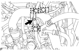
Remove the bolt and wire harness bracket.
-
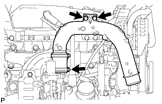
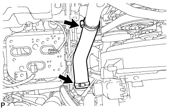
Loosen the hose clamp and remove the 2 bolts and compressor outlet elbow.
-
-
REMOVE VISCOUS WITH MAGNET CLUTCH HEATER ASSEMBLY (for Cold Area Specification Vehicles)
-
Disconnect the viscous heater connector.
-
Disconnect the water by-pass hose and water hose.
-
Remove the 2 bolts and viscous heater with magnet clutch.
-
-
REMOVE NO. 1 VISCOUS HEATER BRACKET SUB-ASSEMBLY (for Cold Area Specification Vehicles)
-
Remove the 4 bolts and No. 1 viscous heater bracket.
-
-
DISCONNECT COOLER COMPRESSOR ASSEMBLY (w/ Air Conditioning System)
-
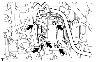
Disconnect the compressor connector.
-
Remove the 4 bolts and disconnect the cooler compressor.
-
-
REMOVE GENERATOR ASSEMBLY
-
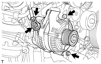
Disconnect the generator connector.
-
Remove the terminal cap.
-
Remove the nut and disconnect the generator wire.
-
Remove the 2 bolts and generator.
-
-
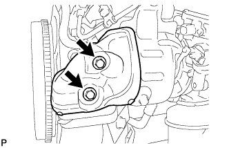
REMOVE GENERATOR BRACKET
-
Remove the bolt and generator bracket.
-
-
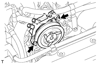
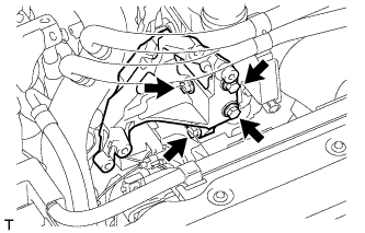
REMOVE NO. 1 COMPRESSOR MOUNTING BRACKET
-
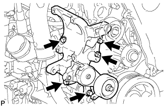
Remove the 5 bolts and No. 1 compressor mounting bracket.
-
-
REMOVE NO. 2 EXHAUST MANIFOLD HEAT INSULATOR
-
Remove the 2 bolts and No. 2 exhaust manifold heat insulator from the turbine outlet elbow.
-
-
REMOVE TURBINE OUTLET ELBOW STAY
-
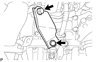
Remove the 2 bolts and turbine outlet elbow stay from the No. 2 turbine outlet elbow and cylinder block sub-assembly.
-
-
REMOVE NO. 2 TURBINE OUTLET ELBOW
-
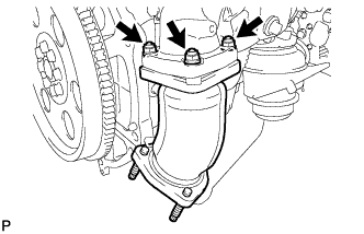
Remove the 3 nuts, No. 2 turbine outlet elbow and gasket from the turbine outlet elbow.
-
-
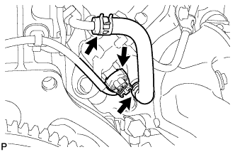
DISCONNECT NO. 1 FUEL PIPE
-
Remove the 2 bolts, union bolt and gasket.
Text in Illustration 
Union Bolt -
Disconnect the No. 1 fuel pipe from the turbine outlet elbow.
-
-
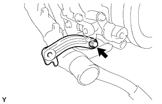
REMOVE FUEL PIPE CLAMP
-
Remove the bolt and fuel pipe clamp from the turbine outlet elbow.
-
-
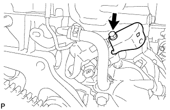
REMOVE NO. 11 WATER BY-PASS HOSE
-
Disconnect the exhaust fuel addition injector connector.
-
Slide the 2 clamps and remove the No. 11 water by-pass hose from the turbine outlet elbow.
-
-
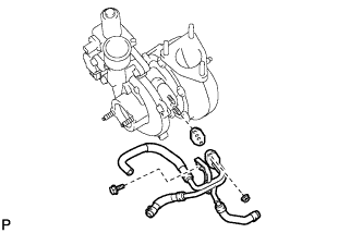
REMOVE TURBINE OUTLET ELBOW
-
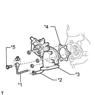
Text in Illustration *1 No. 4 Water By-pass Pipe *2 No. 12 Water By-pass Hose *3 Turbine Outlet Elbow *4 Gasket *5 Union Bolt Remove the union bolt and gasket from the turbine outlet elbow.
-
Slide the clamp and remove the No. 4 water by-pass pipe from the No. 12 water by-pass hose.
-
Remove the 3 nuts, turbine outlet elbow and gasket from the turbocharger sub-assembly.
-
-
DISCONNECT VENTILATION PIPE
-
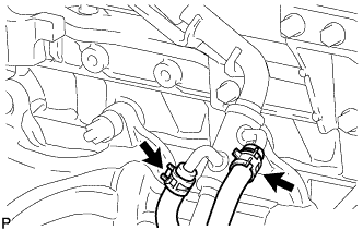
Type A
Slide the 2 clamps and disconnect the No. 3 turbo water hose and No. 4 turbo water hose from the ventilation pipe.
-
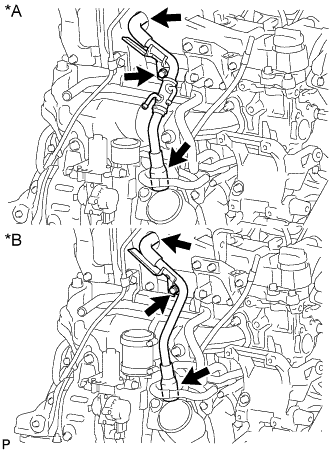
Text in Illustration *A Type A *B Type B Remove the bolt and disconnect the 2 ventilation hoses and ventilation pipe from the cylinder head sub-assembly.
-
-
REMOVE NO. 1 TURBO INSULATOR
-
Remove the 2 bolts and No. 1 turbo insulator from the turbocharger sub-assembly.
-
-
REMOVE NO. 1 EXHAUST MANIFOLD HEAT INSULATOR
-
Remove the 2 bolts and No. 1 exhaust manifold heat insulator from the exhaust manifold.
-
-
DISCONNECT ENGINE OIL LEVEL DIPSTICK GUIDE
-
Remove the bolt.
-
Disconnect the engine oil level dipstick guide from the cylinder block sub-assembly.
-
-
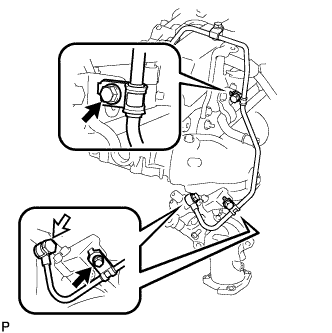
DISCONNECT NO. 1 TURBO WATER HOSE
-
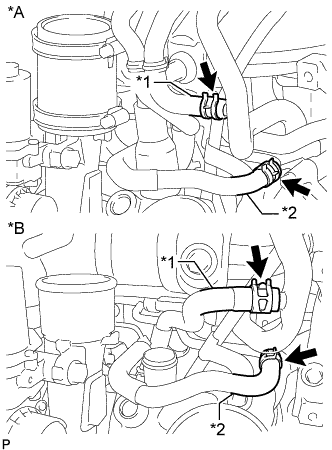
Text in Illustration *A Type A *B Type B *1 No. 1 Turbo Water Hose *2 No. 3 Turbo Water Hose Slide the 2 clamps and disconnect the No. 1 turbo water hose from the No. 2 water by-pass pipe.
-
Type B
Slide the clamp and disconnect the No. 3 turbo water hose from the compressor inlet elbow.
-
-
REMOVE NO. 3 TURBO WATER HOSE
-
Slide the clamp and remove the No. 3 turbo water hose from the No. 2 water by-pass pipe.
-
-
REMOVE TURBOCHARGER STAY
-
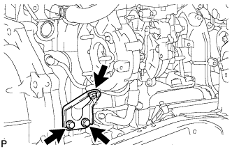
Remove the 2 bolts, nut and turbocharger stay from the turbocharger sub-assembly and cylinder block.
-
-
REMOVE WIRE HARNESS CLAMP BRACKET
-
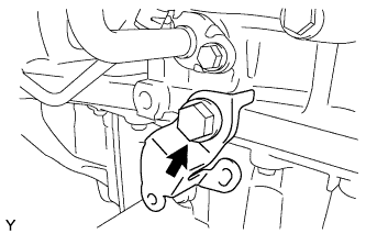
Remove the bolt and wire harness clamp bracket from the cylinder block.
-
-
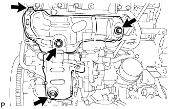
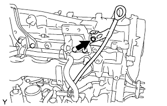
REMOVE TURBO OIL INLET PIPE SUB-ASSEMBLY
-
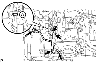
Remove the 2 bolts, 2 nuts, union bolt, turbo oil inlet pipe sub-assembly and 3 gaskets.
Note
Do not loosen the nut labeled A in the illustration.
-
-
REMOVE EXHAUST MANIFOLD WITH TURBOCHARGER SUB-ASSEMBLY
-
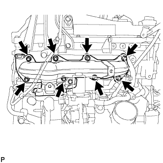
Remove the 8 nuts and 8 plate washers from the exhaust manifold with turbocharger sub-assembly.
-
Remove the exhaust manifold with turbocharger sub-assembly and gasket.
-
-
REMOVE TURBOCHARGER SUB-ASSEMBLY
-
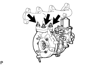
Remove the 3 nuts, turbocharger sub-assembly and gasket.
-
-
REMOVE COMPRESSOR INLET ELBOW
-
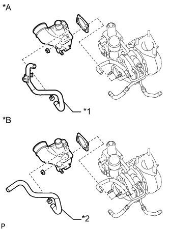
Text in Illustration *A Type A *B Type B *1 No. 4 Turbo Water Hose *2 No. 3 Turbo Water Hose Remove the 2 nuts, compressor inlet elbow and gasket from turbocharger sub-assembly.
-
Type A
Slide the clamp and remove the No. 4 turbo water hose from the compressor inlet elbow.
-
Type B
Slide the clamp and remove the No. 3 turbo water hose from the compressor inlet elbow.
-
-
REMOVE NO. 1 TURBO WATER PIPE SUB-ASSEMBLY
-
Remove the 2 nuts, bolt, No. 1 turbo water pipe sub-assembly and gasket from the turbocharger sub-assembly.
-