AIR SWITCHING VALVE INSTALLATION

-
INSTALL AIR SWITCHING VALVE ASSEMBLY
-
Set the No. 1 exhaust manifold heat insulator in place.
-
Install the air switching valve with 2 new nuts.
- Torque:
- 20 N*m { 204 kgf*cm, 15 ft.*lbf }
-
Connect the connector.
-
w/ Manifold Absolute Pressure Sensor:
Connect the vacuum hose.
-
-
INSTALL NO. 4 INTAKE PIPE
-
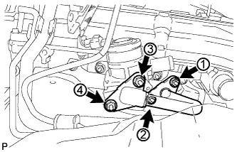
Install 2 new gaskets and the No. 4 intake pipe with 4 new nuts in the order shown in the illustration. Tighten the nuts labeled 1 and 3 to the torque specification again.
- Torque:
- 20 N*m { 204 kgf*cm, 15 ft.*lbf }
-
Check that the nuts are tightened to the torque specification.
-
-
INSTALL NO. 1 EXHAUST MANIFOLD HEAT INSULATOR
-
Install the No. 1 exhaust manifold heat insulator with the 5 bolts.
- Torque:
- 12 N*m { 122 kgf*cm, 9 ft.*lbf }
-
-
CONNECT NO. 1 AIR INJECTION SYSTEM HOSE
-
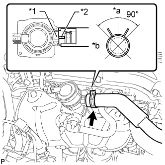
Text in Illustration *1 Rib *2 Paint Mark *a Upper *b RH Side Connect the No. 1 air injection system hose so that its paint mark aligns with the rib of the air switching valve as shown in the illustration.
Tech Tips
-
Make sure the paint mark of the No. 1 air injection system hose is facing upward.
-
Make sure the direction of the hose clamp is as shown in the illustration.
-
-
-
INSTALL FRONT NO. 1 FENDER APRON TO FRAME SEAL RH
-
Install the front No. 1 fender apron to frame seal with the 5 clips.
-
-
INSTALL AIR CLEANER CASE
-
Install the air cleaner case with the 3 bolts.
- Torque:
- 12 N*m { 122 kgf*cm, 9 ft.*lbf }
-
Install the air cleaner filter element.
-
-
INSTALL AIR CLEANER AND HOSE
-
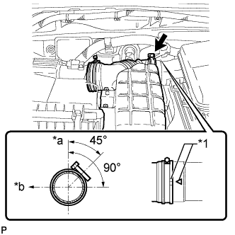
Text in Illustration *1 Matchmark *a Upper Side *b Front Install the air cleaner hose, align its matchmark with the matchmark of the air cleaner cap as shown in the illustration.
-
Tighten the hose clamp.
- Torque:
- 5.0 N*m { 51 kgf*cm, 44 in.*lbf }
-
Attach the 4 clamps.
-
Install the ground wire and clamp with the bolt.
- Torque:
- 8.5 N*m { 87 kgf*cm, 75 in.*lbf }
-
Connect the mass air flow meter connector and attach the 3 clamps.
-