FUEL TANK (for 5 Door) INSTALLATION

-
INSTALL FUEL TANK TO FILLER PIPE HOSE
-
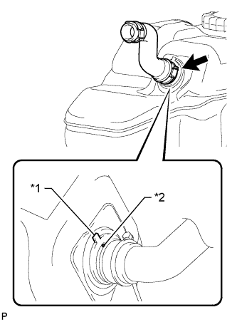
Text in Illustration *1 Fuel Tank Side Mark *2 Hose Side Mark Align the fuel tank side mark with the hose side mark.
-
Install the fuel tank to filler pipe hose to the fuel tank.
-
-
INSTALL NO. 3 FUEL TANK PROTECTOR
-
Install the No. 3 fuel tank protector and attach the 4 clamps.
-
Install the 2 bolts.
- Torque:
- 5.0 N*m { 51 kgf*cm, 44 in.*lbf }
-
-
INSTALL FUEL SUCTION WITH PUMP AND GAUGE TUBE ASSEMBLY
-
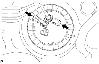
Apply a light coat of gasoline or grease to a new gasket and install the gasket to the fuel tank.
-
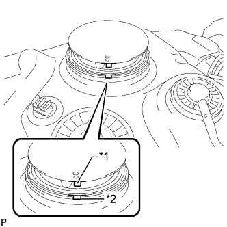
Text in Illustration *1 Protrusion *2 Groove Align the protrusion of the fuel suction with pump and gauge tube with the groove of the fuel tank.
Note
Be careful not to bend the arm of the fuel sender gauge.
-
Install the fuel suction with pump and gauge tube to the fuel tank.
-
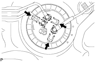
Put a new retainer on the fuel tank. While holding the fuel suction with pump and gauge tube, tighten the retainer one complete turn by hand.
Tech Tips
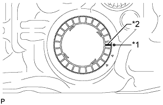
Make sure the start marks on the retainer and fuel tank are aligned and then tighten the retainer.
-
Text in Illustration *1 Start Mark (Fuel Tank Side) *2 Start Mark (Retainer Side) Set SST on the retainer.
- SST
- 09808-14030
Tech Tips
-
Hold the fuel suction tube assembly upright by hand to ensure that the fuel suction tube gasket in not moved out of position.
-
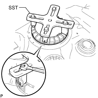
Engage the claws of SST securely with the fuel pump gauge retainer holes to secure SST.
-
Install SST while pressing the claws of SST against the fuel pump gauge retainer (toward the center of SST).
-
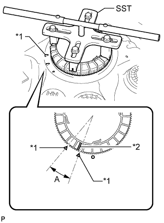
Text in Illustration *1 Fuel Tank Side Mark *2 Retainer Side Mark Using SST, tighten the retainer until the mark on the retainer is within range A on the fuel tank as shown in the illustration.
- SST
- 09808-14030
Tech Tips
Fit the tips of SST onto the ribs of the retainer.
-
-
INSTALL FUEL TANK MAIN TUBE SUB-ASSEMBLY AND FUEL RETURN TUBE SUB-ASSEMBLY (for Single Tank Type)
-
Install the fuel tank main tube and fuel return tube with the 2 fuel tube joint clips.
Note
-
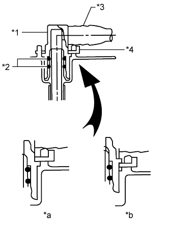
Check that there are no scratches or foreign objects on the connecting parts.
-
Check that the fuel tube joints are inserted securely.
-
Check that the fuel tube joint clips are on the collars of the fuel tube joints.
-
After installing the fuel tube joint clips, check that the fuel tube joints cannot be pulled off.
Text in Illustration *1 Fuel Tube Joint *2 O-Ring *3 Fuel Tube *4 Fuel Tube Joint Clip *a CORRECT *b INCORRECT
-
-
Install the fuel tank main tube and fuel return tube to the fuel tank.
-
-
INSTALL FUEL TANK MAIN TUBE SUB-ASSEMBLY, FUEL RETURN TUBE SUB-ASSEMBLY AND NO. 2 FUEL MAIN TUBE SUB-ASSEMBLY (for Double Tank Type)
-
Install the fuel tank main tube, fuel return tube and No. 2 fuel main tube with the 3 fuel tube joint clips.
Note
-
Check that there are no scratches or foreign objects on the connecting parts.
-
Check that the fuel tube joints are inserted securely.
-
Check that the fuel tube joint clips are on the collars of the fuel tube joints.
-
After installing the fuel tube joint clips, check that the fuel tube joints cannot be pulled off.
Text in Illustration *1 Fuel Tube Joint *2 O-Ring *3 Fuel Tube *4 Fuel Tube Joint Clip *a CORRECT *b INCORRECT
-
-
Install the fuel tank main tube and fuel return tube to the fuel tank.
-
Install the No. 2 fuel main tube to the fuel tank and attach the clamp.
-
-
INSTALL FUEL TANK CUSHION
-
Install 3 new fuel tank cushions to the fuel tank.
-
-
INSTALL FUEL TANK SUB-ASSEMBLY
-
Set the fuel tank on a transmission jack and lift up the transmission jack.
Note
Do not allow the fuel tank to contact the vehicle, especially the differential.
-
Install the 2 fuel tank bands with the 2 pins and 2 clips.
-
Connect the 2 fuel tank bands with the 2 bolts.
- Torque:
- 40 N*m { 408 kgf*cm, 30 ft.*lbf }
-
-
CONNECT FUEL TANK TO FILLER PIPE HOSE
-
Connect the fuel tank to filler pipe hose to the filler pipe.
-
-
CONNECT FUEL CUT OFF TUBE (for Single Tank Type)
-
Connect the fuel cut off tube Click here.
-
-
CONNECT FUEL CUT OFF TUBE (for Double Tank Type)
-
Connect the fuel cut off tube Click here.
-
-
CONNECT FUEL TANK BREATHER TUBE SUB-ASSEMBLY (for Single Tank Type)
-
Connect the fuel tank breather tube Click here.
-
-
CONNECT FUEL TANK BREATHER TUBE SUB-ASSEMBLY (for Double Tank Type)
-
Connect the fuel tank breather tube Click here.
-
-
CONNECT NO. 2 FUEL MAIN TUBE SUB-ASSEMBLY (for Double Tank Type)
-
Connect the No. 2 fuel main tube Click here.
-
-
CONNECT FUEL RETURN TUBE SUB-ASSEMBLY
-
Connect the fuel return tube Click here.
-
-
CONNECT FUEL TANK MAIN TUBE SUB-ASSEMBLY
-
Connect the fuel tank main tube Click here.
-
-
INSTALL NO. 1 FUEL TANK PROTECTOR SUB-ASSEMBLY
-
Install the No. 1 fuel tank protector with the 6 bolts.
- Torque:
- 20 N*m { 204 kgf*cm, 15 ft.*lbf }
-
-
INSTALL REAR FLOOR SERVICE HOLE COVER
-
Connect the fuel pump and fuel sender gauge connector.
-
Install the rear floor service hole cover with the 3 screws.
-
-
INSTALL REAR SEAT ASSEMBLY LH
-
for 60/40 Split Double-folding Seat Type LH Side:
Install the rear seat assembly LH Click here.
-
for 60/40 Split Slide Walk-in Seat Type LH Side:
Install the rear seat assembly LH Click here.
-
-
CONNECT CABLE TO NEGATIVE BATTERY TERMINAL
Note
When disconnecting the cable, some systems need to be initialized after the cable is reconnected Click here.
-
INSPECT FOR FUEL LEAK
-
Make sure that there are no fuel leaks after performing maintenance on the fuel system.
-
Connect the intelligent tester to the DLC3.
-
Turn the ignition switch to ON and turn the intelligent tester on.
Note
Do not start the engine.
-
Enter the following menus: Powertrain / Engine and ECT / Active Test / Control the Fuel Pump / Speed.
-
Check that there are no leaks from the fuel system.
If there are fuel leaks, repair or replace parts as necessary.
-
Turn the ignition switch off.
-
Disconnect the intelligent tester from the DLC3.
-
-