FUEL SUPPLY PUMP (w/ DPF) REMOVAL

Note
-
When replacing the injector assemblies (including shuffling the injector assemblies between the cylinders), common rail assembly or cylinder head sub-assembly, it is necessary to replace the injection pipe sub-assemblies with new ones.
-
When replacing the fuel supply pump assembly, common rail assembly, cylinder block sub-assembly, cylinder head sub-assembly, cylinder head gasket or timing gear case assembly, it is necessary to replace the fuel inlet pipe sub-assembly with a new one.
-
After removing the injection pipe sub-assemblies and fuel inlet pipe sub-assembly, clean them with a brush and compressed air.
-
DISCONNECT CABLE FROM NEGATIVE BATTERY TERMINAL
Note
-
After turning the engine switch off, waiting time may be required before disconnecting the cable from the battery terminal. Therefore, make sure to read the disconnecting the cable from the battery terminal notice before proceeding with work Click here.
-
When disconnecting the cable, some systems need to be initialized after the cable is reconnected Click here.
-
-
REMOVE COWL TOP VENTILATOR LOUVER SUB-ASSEMBLY
-
REMOVE TIMING BELT
-
REMOVE ELECTRIC EGR CONTROL VALVE ASSEMBLY
-
DISCONNECT WIRE HARNESS
-
Remove the bolt and disconnect the wire harness.
-
for LHD:
Remove the bolt and disconnect the wire harness.
-
Detach the 5 clamps and disconnect the wire harness from the cowl top panel.
-
-
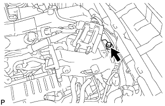
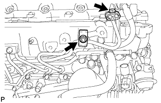
REMOVE MANIFOLD ABSOLUTE PRESSURE SENSOR
-
Disconnect the manifold absolute pressure sensor connector and vacuum hose.
-
Remove the bolt and manifold absolute pressure sensor.
-
-
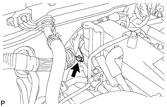
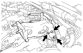
REMOVE EMISSION CONTROL VALVE BRACKET
-
Remove the bolt and emission control valve bracket.
-
-
REMOVE THROTTLE BODY BRACKET
-
Remove the 3 bolts and throttle body bracket.
-
-
REMOVE NO. 1 GAS FILTER
-
Disconnect the vacuum hose and remove the No. 1 gas filter from the gas filter bracket.
-
-
REMOVE GAS FILTER BRACKET
-
Detach the clamp and disconnect the wire harness.
-
Remove the bolt and gas filter bracket.
-
-
REMOVE INTAKE AIR CONNECTOR
-
Remove the 3 bolts, intake air connector and gasket.
-
-
REMOVE NO. 4 INJECTION PIPE SUB-ASSEMBLY
-
Remove the bolt, nut and 2 No. 2 injection pipe clamps.
-
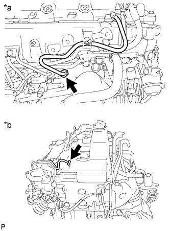
Text in Illustration *a Common Rail Assembly Side *b Injector Assembly Side Using a 17 mm union nut wrench, loosen the union nuts and remove the No. 4 injection pipe sub-assembly.
-
-
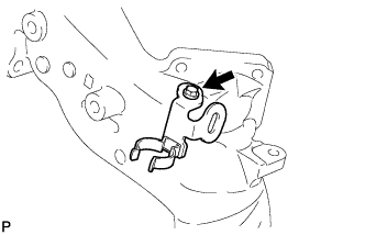
REMOVE NO. 2 FUEL PIPE
-
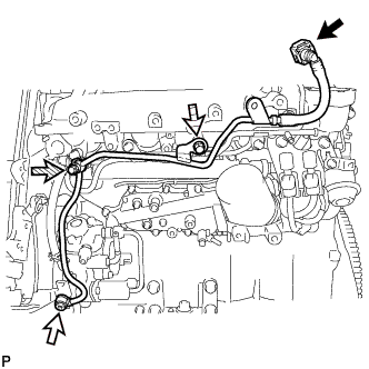
Disconnect the fuel tube connector Click here.
Text in Illustration 
Fuel Tube Connector 
Union Bolt 
Fuel Check Valve 
Bolt -
Using a 6 mm hexagon wrench, remove the union bolt and gasket.
-
Remove the fuel check valve and gasket.
-
Remove the bolt and No. 2 fuel pipe.
-
-
REMOVE INJECTION PUMP INSULATOR
-
REMOVE NO. 1 INJECTION PUMP PROTECTOR
-
Remove the 2 bolts and No. 1 injection pump protector.
-
-
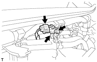
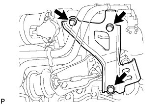
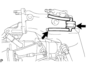
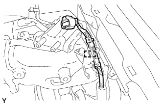
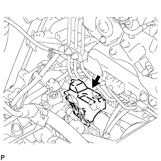
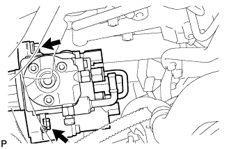
REMOVE FUEL SUPPLY PUMP ASSEMBLY
-
Disconnect the 2 fuel hoses.
-
Disconnect the suction control valve connector and fuel temperature sensor connector from the fuel supply pump assembly.
-
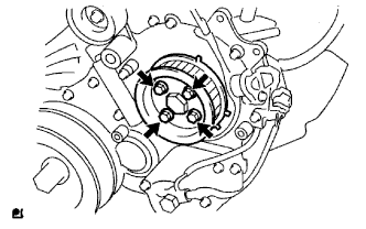
Remove the 4 bolts indicated by the arrows in the illustration.
-
Remove the No. 2 camshaft timing pulley flange and pump drive shaft pulley.
-
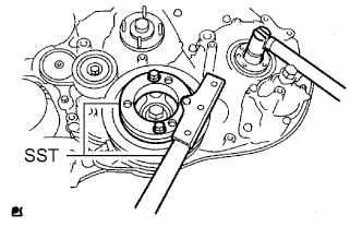
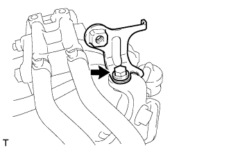
Remove the set nut and O-ring while holding the crankshaft pulley using SST.
- SST
- 09213-58014
- 09330-00021
-
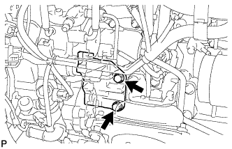
Loosen the 2 nuts.
-
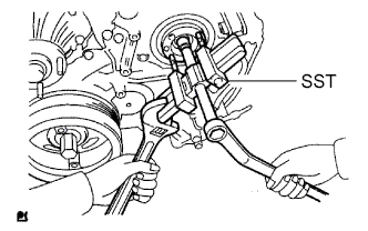
Using SST, disconnect the fuel supply pump assembly from the injection gear.
- SST
- 09950-50013 ( 09951-05010, 09952-05010, 09953-05020, 09954-05021 )
Note
Apply lubricant to the threads and tip of SST (center bolt) before using it.
-
Remove the 2 nuts and fuel supply pump assembly.
Note
-
Do not hold or carry the fuel supply pump assembly by holding the pipe.
-
The fuel supply pump assembly must be kept horizontal.
-
-
Remove the O-ring.
-