FUEL INJECTOR (w/o DPF) REMOVAL

Note
-
When replacing the injectors (including shuffling the injectors between the cylinders), common rail or cylinder head, it is necessary to replace the injection pipes with new ones.
-
When replacing the fuel supply pump, common rail, cylinder block, cylinder head, cylinder head gasket or timing gear case, it is necessary to replace the fuel inlet pipe with a new one.
-
After removing the injection pipes, clean them with a brush and compressed air.
-
DISCONNECT CABLE FROM NEGATIVE BATTERY TERMINAL
Note
-
After turning the ignition switch off, waiting time may be required before disconnecting the cable from the battery terminal. Therefore, make sure to read the disconnecting the cable from the battery terminal notice before proceeding with work Click here.
-
When disconnecting the cable, some systems need to be initialized after the cable is reconnected Click here.
-
-
REMOVE ELECTRIC EGR CONTROL VALVE ASSEMBLY (w/ EGR System)
-
Remove the electric EGR control valve assembly Click here.
-
-
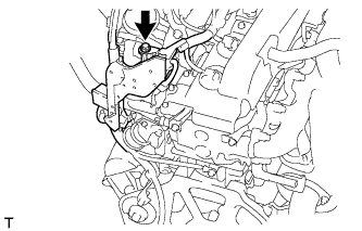
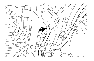
DISCONNECT INLET HEATER WATER HOSE (w/o EGR System)
-
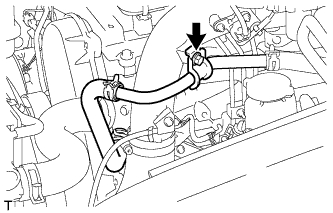
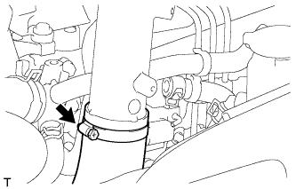
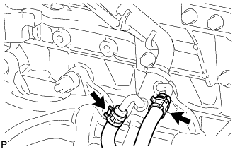
Remove the bolt and disconnect the inlet heater water hose.
-
-
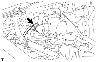
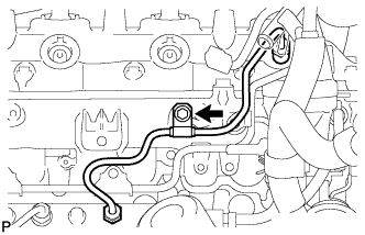
DISCONNECT NO. 4 VACUUM TRANSMITTING PIPE SUB-ASSEMBLY (w/o EGR System)
-
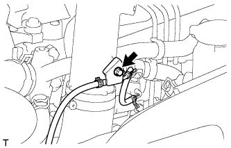
Remove the bolt and disconnect the No. 4 vacuum transmitting pipe.
-
-
REMOVE NO. 1 INTAKE PIPE (w/o EGR System)
-
Disconnect the 3 connectors from the intake air temperature sensor, throttle control motor and manifold absolute pressure sensor.
-
Detach the 2 clamps.
-
Disconnect the vacuum hose from the manifold absolute pressure sensor.
-
Loosen the 2 hose clamps of the No. 1 air hose.
-
Loosen the hose clamp of the intercooler air hose.
-
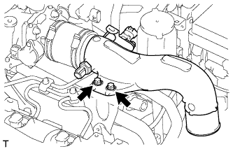
Remove the 2 bolts and No. 1 intake pipe.
-
-
REMOVE THROTTLE BODY BRACKET (w/o EGR System)
-
Disconnect the vacuum hose.
-
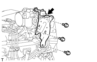
Remove the bolt and gas filter with gas filter bracket.
-
Remove the 2 bolts and throttle body bracket.
-
-
REMOVE NO. 1, NO. 2 AND NO. 3 INJECTION PIPE SUB-ASSEMBLY (w/o EGR System)
Note
-
After removing the injection pipe, cover the outlets on the common rail with tape to keep out foreign matter.
-
After removing the injection pipe, put it in a plastic bag to prevent foreign matter from contaminating its injector inlet.
-
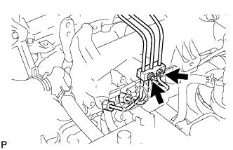
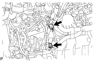
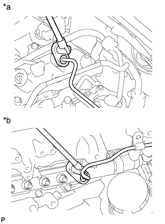
Remove the 2 nuts and No. 3 injection pipe clamp.
-
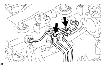
Remove the 2 bolts and 2 No. 2 injection pipe clamps.
-
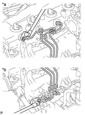
Text in Illustration *a Injector Side *b Common Rail Side Using a 17 mm union nut wrench, loosen the union nuts and remove the No. 1, No. 2 and No. 3 injection pipes.
-
-
REMOVE AIR CONNECTOR STAY (w/o EGR System)
-
Remove the 3 bolts and air connector stay.
-
-
DISCONNECT ENGINE WIRE (w/o EGR System)
-
for LHD:
Remove the 2 bolts and disconnect the clamp and engine wire.
-
for RHD:
Remove the bolt and disconnect the engine wire.
-
-
REMOVE INTAKE AIR CONNECTOR WITH DIESEL THROTTLE BODY ASSEMBLY (w/o EGR System)
-
Disconnect the throttle position sensor connector.
-
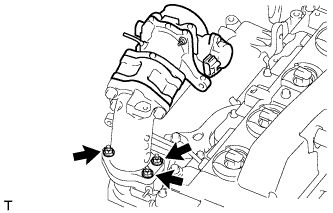
Remove the 3 bolts, intake air connector with diesel throttle and gasket.
-
-
REMOVE MANIFOLD STAY WITH VACUUM SWITCHING VALVE
-
Disconnect the vacuum switching valve connector.
-
w/o EGR System:
Disconnect the connector.
-
w/ EGR System without EGR Cooler:
Disconnect the 2 connectors.
-
w/ EGR System with EGR Cooler:
Disconnect the 3 connectors.
-
-
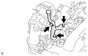
Disconnect the No. 1 vacuum transmitting hose.
-
w/ EGR System:
Disconnect the No. 2 vacuum transmitting hose and No. 3 vacuum transmitting hose.
-
w/ EGR Cooler:
Disconnect the No. 3 vacuum transmitting hose.
-
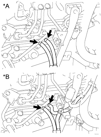
Text in Illustration *A w/o EGR System *B w/ EGR System Disconnect the No. 3 vacuum transmitting hose and No. 4 vacuum transmitting hose.
-
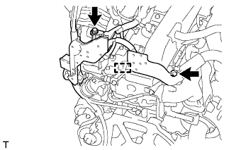
Remove the 2 bolts and manifold stay with vacuum switching valve.
-
-
REMOVE NO. 4 INJECTION PIPE SUB-ASSEMBLY
-
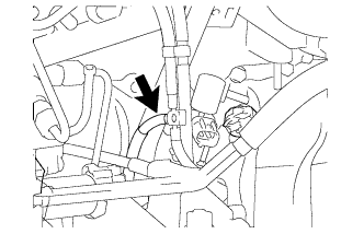
Remove the bolt and detach the injection pipe clamp.
Note
If an injection pipe clamp is removed from the No. 4 injection pipe, replace the injection clamp with a new one.
-
Text in Illustration *a Injector Side *b Common Rail Side Using a 17 mm union nut wrench, loosen the union nuts and remove the No. 4 injection pipe.
-
-
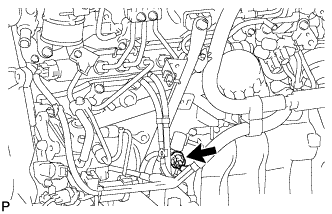
REMOVE OIL FILTER SUB-ASSEMBLY
-
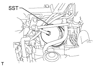
Using SST, remove the oil filter.
- SST
- 09228-07501
-
-
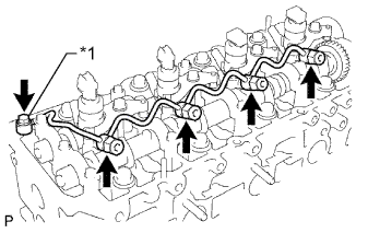
REMOVE NO. 2 NOZZLE LEAKAGE PIPE ASSEMBLY
-
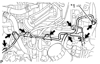
Text in Illustration *1 Union Bolt Disconnect the 3 fuel hoses.
-
Remove the union bolt, 4 bolts, No. 2 nozzle leakage pipe and gasket.
-
-
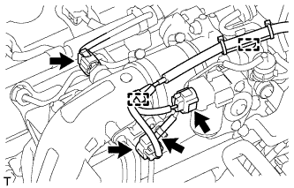
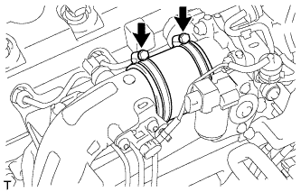
REMOVE VENTILATION PIPE
-
Type A
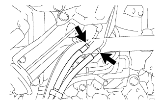
Slide the 2 clamps and disconnect the No. 3 turbo water hose and No. 4 turbo water hose from the ventilation pipe.
-
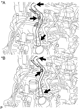
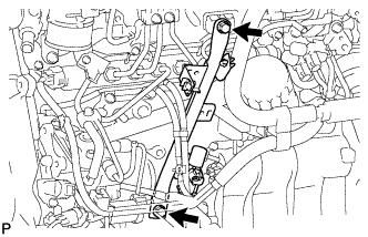
Text in Illustration *A Type A *B Type B Remove the bolt and disconnect the 2 ventilation hoses and ventilation pipe from the cylinder head sub-assembly.
-
-
REMOVE NO. 2 CYLINDER HEAD COVER SUB-ASSEMBLY
-
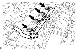
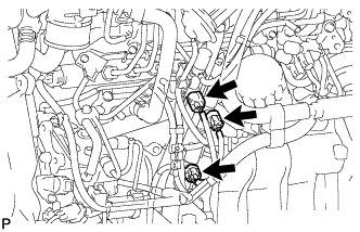
Disconnect the 4 injector connectors.
-
Detach the 2 wire harness clamps and disconnect the wire harness from the No. 2 cylinder head cover.
-
Remove the 4 bolts and No. 2 cylinder head cover.
-
-
REMOVE CYLINDER HEAD COVER SUB-ASSEMBLY
Note
If the cylinder head cover is removed, replace the 4 No. 3 cylinder head cover gaskets with new ones.
-
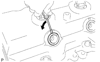
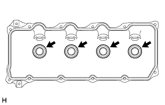
Using a small screwdriver, remove the nozzle holder seal by prying the portion between the nozzle holder seal and the cutout part of the cylinder head cover.
-
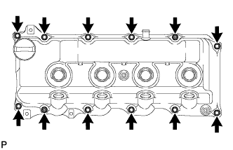
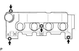
Remove the 10 bolts, 2 nuts, cylinder head cover and cylinder head cover gasket.
-
Remove the 4 No. 3 cylinder head cover gaskets from the cylinder head cover.
-
-
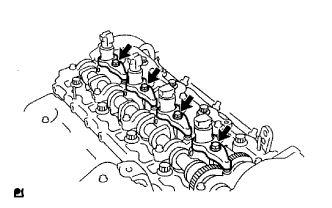
REMOVE INJECTOR ASSEMBLY
-
Text in Illustration *1 Union Bolt Remove the union bolt, 4 injector hollow screws, 5 gaskets and nozzle leakage pipe.
Note
-
When removing the nozzle leakage pipe, place a cushion under the pipe.
-
Be careful not to deform or scratch the union seal surface.
-
After removing the nozzle leakage pipe, put it in a plastic bag to prevent foreign matter from contaminating its injector inlet.
-
-
Remove the 4 bolts, 4 washers, 4 No. 1 nozzle holder clamps and 4 injectors.
Tech Tips
Arrange the injectors, No. 1 nozzle holder clamps, washers and bolts in the correct order.
-
Remove the O-ring from each injector.
-
Remove the 4 injection nozzle seats from the cylinder head.
-