- Click here
INSTALL STUD BOLT
Note: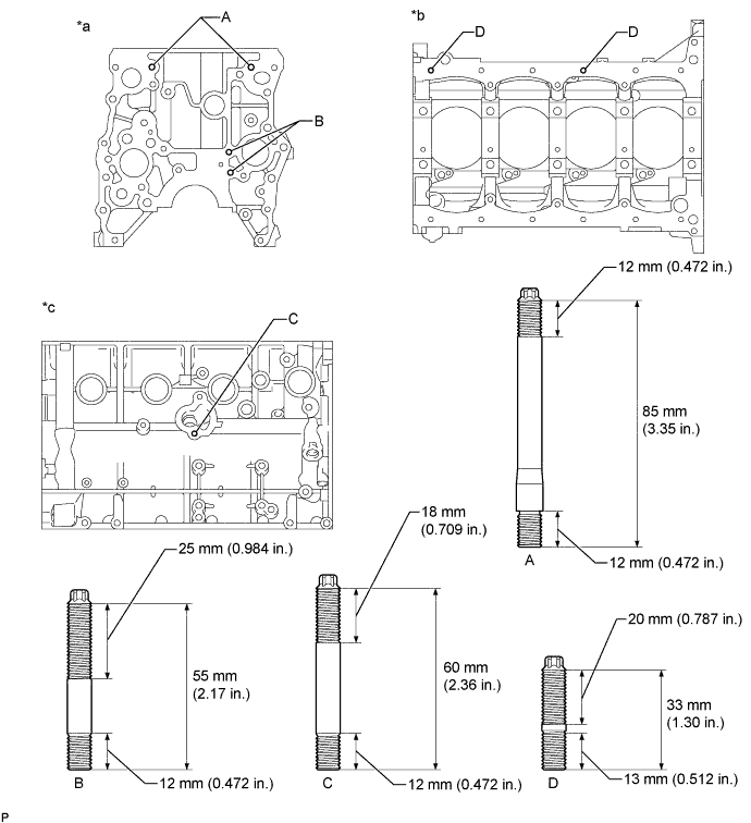
If a stud bolt is deformed or its threads are damaged, replace it.
Table 1. Text in Illustration *a Front Side *b Lower Side *c Exhaust Side - -
-
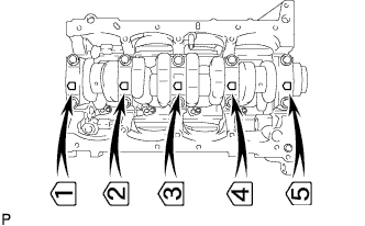
Using an E8 "TORX" socket wrench, install the stud bolts labeled A.
7.5 N*m 76 kgf*cm 66 in.*lbf -
Using an E7 "TORX" socket wrench, install the stud bolts labeled B and D.
7.5 N*m 76 kgf*cm 66 in.*lbf -
Apply adhesive to the hole for the stud bolt labeled C in the cylinder block. Using an E7 "TORX" socket wrench, install the stud bolt labeled C.
7.5 N*m 76 kgf*cm 66 in.*lbf Tip:When reusing a stud bolt, apply adhesive to the bolt before installing it.
Adhesive Toyota Genuine Adhesive 1344, Three Bond 1344 or equivalent
-
- Click here
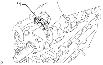
INSTALL CYLINDER BLOCK WATER DRAIN COCK SUB-ASSEMBLY
-
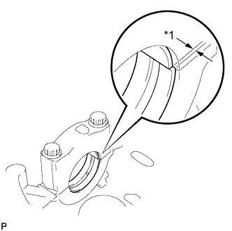
Apply adhesive to the drain cock.
Adhesive Toyota Genuine Adhesive 1324, Three Bond 1324 or equivalent -
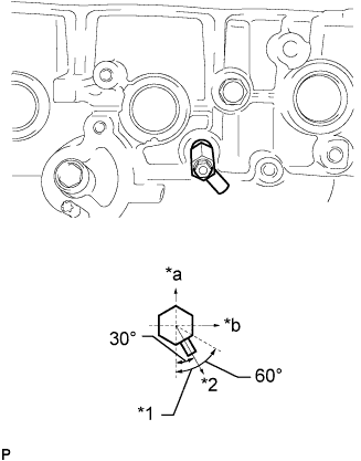
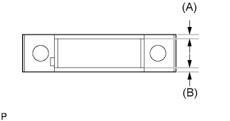
Install the cylinder block water drain cock as shown in the illustration.
25 N*m 250 kgf*cm 18 ft.*lbf Table 2. Text in Illustration *1 Allowable Range *2 Target Direction *a Upper Side *b Front Note:
-
Do not rotate the drain cock more than 1 revolution (360°) after tightening the drain cock to the specified torque.
-
Do not loosen the drain cock to adjust it. If an adjustment is necessary, remove the drain cock and reinstall it.
-
-
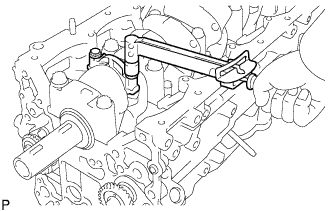
Install the water drain cock plug to the water drain cock sub-assembly.
13 N*m 130 kgf*cm 9 ft.*lbf
-
- Click here
INSTALL NO. 1 OIL NOZZLE SUB-ASSEMBLY
-
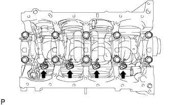
Using a 5 mm hexagon wrench, install the oil nozzles.
7.0 N*m 71 kgf*cm 62 in.*lbf
-
- Click here
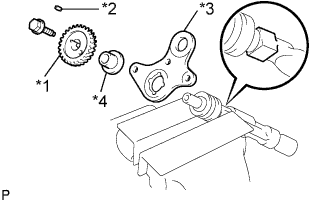
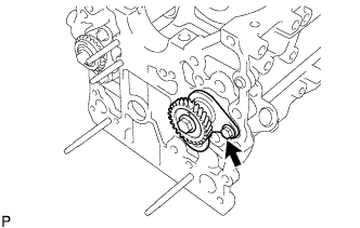
INSTALL NO. 2 BALANCE SHAFT DRIVEN GEAR
-
Mount the head portion of the balance shaft in a vise.
Note:Do not damage the balance shaft.
-
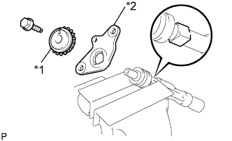
Install the No. 2 balance shaft thrust washer and No. 2 balance shaft driven gear.
Table 3. Text in Illustration *1 No. 2 Balance Shaft Driven Gear *2 No. 2 Balance Shaft Thrust Washer -
Install the bolt.
36 N*m 367 kgf*cm 27 ft.*lbf
-
- Click here
INSTALL NO. 2 BALANCE SHAFT
-
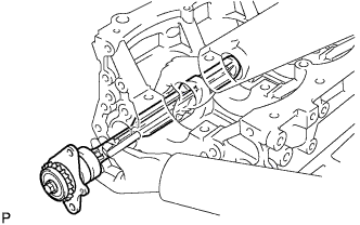
Install the balance shaft to the cylinder block.
Note:When installing the balance shaft, be sure to support the balance shaft with both hands and avoid scratching the balance shaft bearing on the cylinder block.
-
Install the 2 bolts.
18 N*m 184 kgf*cm 13 ft.*lbf
-
- Click here
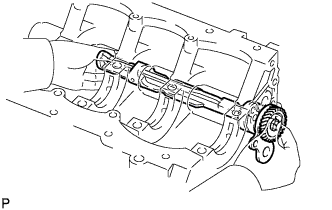
INSTALL NO. 1 BALANCE SHAFT DRIVEN GEAR
-
Mount the head portion of the balance shaft in a vise.
Note:Do not damage the balance shaft.
-
Install the No. 1 balance shaft thrust washer, balance shaft thrust spacer, sliding key and No. 1 balance shaft driven gear.
Table 4. Text in Illustration *1 No. 1 Balance Shaft Driven Gear *2 Sliding Key *3 Balance Shaft Thrust Washer *4 Balance Shaft Thrust Spacer -
Install the bolt.
36 N*m 367 kgf*cm 27 ft.*lbf
-
- Click here
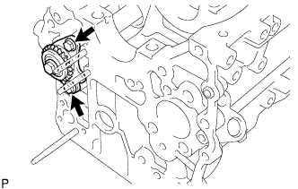
INSTALL NO. 1 BALANCE SHAFT
-
Install the No. 1 balance shaft to the cylinder block.
Note:When installing the balance shaft, be sure to support the balance shaft with both hands and avoid scratching the balance shaft bearing on the cylinder block.
-
Install the bolt.
18 N*m 184 kgf*cm 13 ft.*lbf
-
- Click here
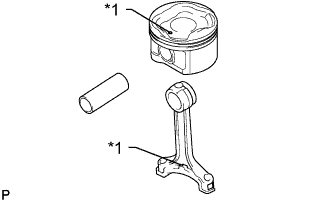
INSTALL PISTON WITH PIN SUB-ASSEMBLY
-
Assemble the piston and connecting rod.
-
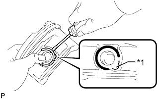
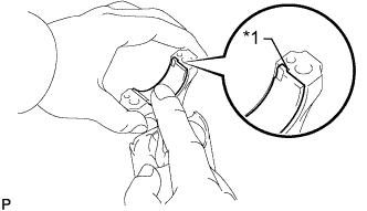
Using a screwdriver, install a new snap ring at one end of the piston pin hole.
Table 5. Text in Illustration *1 Service Hole Tip:Make sure that the end gap of the snap ring is not aligned with the service hole cutout portion of the piston.
-
Gradually heat the piston to approximately 80 to 90°C (176 to 194°F).
-
Coat the piston pin with engine oil.
-
Align the front marks of the piston and connecting rod and push in the piston pin with your thumb.
Table 6. Text in Illustration *1 Front Mark Tip:The piston and pin are a matched set.
-
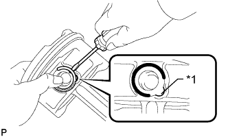
Using a screwdriver, install a new snap ring at the other end of the piston pin hole.
Table 7. Text in Illustration *1 Service Hole Tip:Make sure that the end gap of the snap ring is not aligned with the service hole cutout portion of the piston.
-
Check the fitting condition between the piston and piston pin by trying to move the piston back and forth on the piston pin.
-
-
- Click here
INSTALL PISTON RING SET
-
Install the oil ring expander by hand.
-
Using a piston ring expander, install the oil ring rail.
-
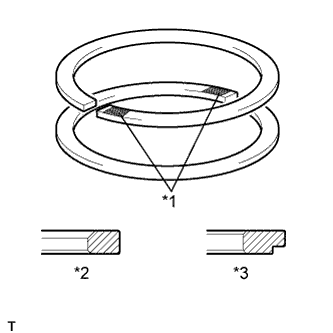
Using a piston ring expander, install the 2 compression rings so that the painted marks are positioned as shown in the illustration.
Tip:
-
Install the No. 1 compression ring with the code mark (1N) facing upward.
-
Install the No. 2 compression ring with the code mark (2N) facing upward.
Table 8. Text in Illustration *1 Code Mark *2 No. 1 Compression Ring *3 No. 2 Compression Ring -
-
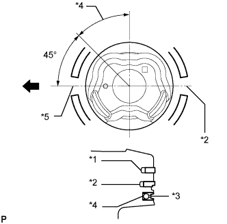
Position the piston rings so that the ring ends are as shown in the illustration.
Table 9. Text in Illustration *1 No. 1 Compression Ring *2 No. 2 Compression Ring *3 Oil Ring *4 Oil Ring Expander *5 No. 1 Compression Ring and Oil Ring 
Front Note:Do not align the compression ring ends.
-
- Click here
INSTALL CRANKSHAFT BEARING
Tip:The crankshaft bearing cap bolts are tightened in 2 progressive steps.
Note:Do not apply engine oil to the contact area or backside of the bearing.
-
Clean the main journal and both surfaces of the bearing.
-
Install the upper bearing.
-
Install the upper bearing to the cylinder block as shown in the illustration.
Reference (Difference in Dimension of Cylinder Block and Bearing) Item Specified Condition # 1, 5 journal 3.75 mm (0.148 in.) # 3 journal 1.74 mm (0.0684 in.) # 2, 4 journal 2.75 mm (0.108 in.) Note:
-
Do not apply engine oil to the bearings or their contact surfaces.
-
Both sides of the oil groove in the cylinder block should be visible through the oil feed holes in the bearing. The amount visible on each side of the holes should be equal.
Table 10. Text in Illustration *1 Oil Groove *a CORRECT *b INCORRECT -
-
-
Install the lower bearing.
-
Install the lower bearing to the bearing cap.
-
Using a vernier caliper, measure the distance between the bearing cap edge and lower bearing edge.
Dimension A - B or B - A 0.3 mm (0.0118 in.) or less Reference (Dimension of A or B) Item Specified Condition # 1, 5 journal 3.75 mm (0.148 in.) # 3 journal 1.75 mm (0.0689 in.) # 2, 4 journal 2.75 mm (0.108 in.) Note:Do not apply engine oil to the bearings or their contact surfaces.
-
-
With the upper bearing and lower bearing installed, use a plastic-faced hammer to install the bearing caps to the cylinder block.
Note:Make sure that the bearing caps are installed in the correct positions and facing in the correct direction.
-
Using a vernier caliper, measure the amount of misalignment between the upper bearing and lower bearing as shown in the illustration.
Standard misalignment 0.9 mm (0.0354 in.) or less Table 11. Text in Illustration *1 Misalignment -
Remove the bearing cap.
-
Apply engine oil to the thrust washers.
-
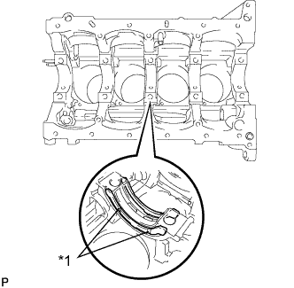
Install the 2 thrust washers to the No. 3 journal position of the cylinder block with the oil grooves facing outward.
Table 12. Text in Illustration *1 Oil Groove Note:Be careful when installing the upper and lower thrust washers as they are similar but cannot be interchanged.
-
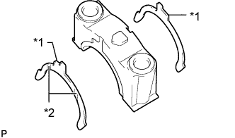
Install the 2 thrust washers to the No. 3 bearing cap with the grooves facing outward.
Table 13. Text in Illustration *1 Claw *2 Oil Groove Note:Be careful when installing the thrust bearing upper and lower as they are similar but cannot be interchanged. The bearing lower has a claw as shown in the illustration.
-
Apply engine oil to the lower bearing.
-
- Click here
INSTALL CRANKSHAFT
-
Apply engine oil to the upper bearing, and then place the crankshaft on the cylinder block.
-
Install the 5 crankshaft bearing caps in their proper locations.
-
Install the crankshaft bearing cap bolt.
-
Apply a light coat of engine oil to the threads and under the heads of the bearing cap bolts.
-
Temporarily install the crankshaft bearing cap bolts.
Tip:The main bearing cap bolts are tightened in 2 progressive steps.
-
Step 1:
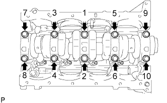
Uniformly tighten the 10 main bearing cap bolts in the sequence shown in the illustration.
39 N*m 398 kgf*cm 29 ft.*lbf If any of the main bearing cap bolts does not meet the torque specification, replace the main bearing cap bolt.
-
Mark the front of the bearing cap bolts with paint.
-
Step 2:
Tighten the bearing cap bolts 90° in the sequence shown in step 1.
-
Check that the paint marks are now at a 90° angle to the front.
-
-
Check that the crankshaft turns smoothly.
-
Check the crankshaft thrust clearance (Click here).
-
- Click here
INSTALL CONNECTING ROD BEARING
-
Align the bearing claw with the groove of the connecting rod or connecting rod cap.
Table 14. Text in Illustration *1 Claw -
Install the bearings to the connecting rod and connecting rod cap.
Note:Clean the backside of the bearing and the surface of the connecting rod or connecting rod cap that contacts the bearing.
-
- Click here
INSTALL PISTON SUB-ASSEMBLY WITH CONNECTING ROD
-
Apply engine oil to the cylinder walls, the pistons, and the surfaces of the connecting rod bearings.
-
Position the piston rings so that the ring ends are as shown in the illustration.
Table 15. Text in Illustration *1 No. 1 Compression Ring *2 No. 2 Compression Ring *3 Oil Ring *4 Oil Ring Expander *5 No. 1 Compression Ring and Oil Ring Front Note:Do not align the compression ring ends.
-
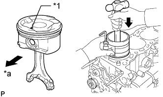
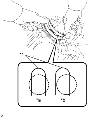
Using a piston ring compressor, push the numbered piston and connecting rod assembly into the correct cylinder with the front mark of the piston facing forward.
Table 16. Text in Illustration *1 Front Mark *a Front -
Match the numbered connecting rod cap with the correct connecting rod.
-
Check that the front mark of the connecting rod cap is facing forward.
Table 17. Text in Illustration *1 Front Mark -
Install the connecting rod cap bolts.
Tip:The connecting rod cap bolts are tightened in 2 progressive steps.
-
Apply a light coat of engine oil to the threads and under the heads of the connecting rod cap bolts.
-
Step 1:
Install and alternately tighten the bolts of the connecting rod cap in several steps.
25 N*m 250 kgf*cm 18 ft.*lbf -
Mark the front of each connecting rod cap bolt with paint.
-
Step 2:
Tighten the cap bolts 90° as shown.
-
Check that the painted marks are now at a 90° angle to the front.
-
-
Check that the crankshaft turns smoothly.
-
Check the connecting rod thrust clearance (Click here).
-