CYLINDER BLOCK REPLACEMENT

-
REPLACE CONNECTING ROD SMALL END BUSH
-
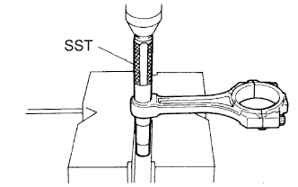
Using SST and a press, press out the bush.
- SST
- 09222-30010
-
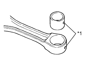
Text in Illustration *1 Oil Hole Align the oil holes of a new bush and the connecting rod.
-
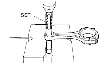
Using SST and a press, press in the bush.
- SST
- 09222-30010
-
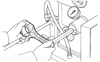
Using a pin hole grinder, hone the bush to obtain the standard specified clearance between the bush and piston pin.
-
Check that the piston pin fits at normal room temperature.
-
Coat the piston pin with engine oil and push it into the connecting rod with your thumb.
-
-
-
REPLACE TIGHT PLUG
Note
If coolant leaks from the tight plug or the plug is corroded, replace it.
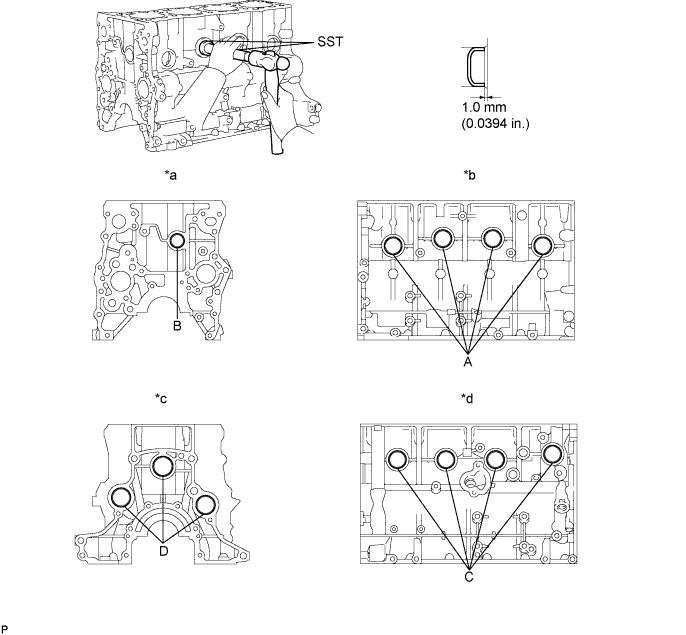
Text in Illustration *a Front Side *b Intake Side *c Rear Side *d Exhaust Side
-
Apply adhesive to new tight plugs.
Adhesive Toyota Genuine Adhesive 1324, Three Bond 1324 or equivalent. -
Using SST, tap in the 8 tight plugs labeled A and C.
- SST
- 09950-60010 ( 09951-00350 )
- 09950-70010 ( 09951-07100 )
-
Using SST, tap in the tight plug labeled B.
- SST
- 09950-60010 ( 09951-00300 )
- 09950-70010 ( 09951-07100 )
-
Using SST, tap in the 3 tight plugs labeled D.
- SST
- 09950-60010 ( 09951-00400 )
- 09950-70010 ( 09951-07100 )
-
-
REPLACE STRAIGHT PIN
Note
It is not necessary to remove a straight pin unless it is being replaced.
-
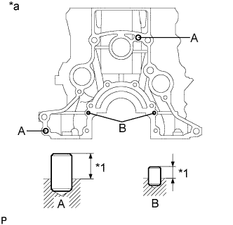
Text in Illustration *1 Protrusion *a Rear Side Using a plastic-faced hammer, tap in new straight pins to the cylinder block.
Standard Straight Pin Item Wide Protrusion Pin A 10 mm (0.394 in.) 13 mm (0.512 in.) Pin B 6.0 mm (0.236 in.) 5.5 mm (0.217 in.)
-
-
REPLACE RING PIN
Note
It is not necessary to remove a ring pin unless it is being replaced.
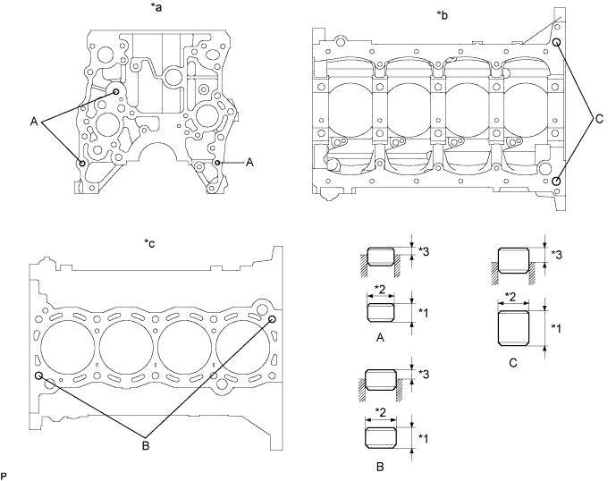
Text in Illustration *1 Height *2 Width *3 Protrusion - - *a Front Side *b Lower Side *c Upper Side - -
-
Using a plastic-faced hammer, tap in new ring pins to the cylinder block.
Standard Ring Pin Item Height Width Protrusion Pin A 9.0 mm (0.354 in.) 11 mm (0.433 in.) 3.5 to 4.5 mm (0.138 to 0.177 in.) Pin B 14 mm (0.511 in.) 15 mm (0.591 in.) 7.5 to 9.5 mm (0.295 to 0.374 in.) Pin C 20 mm (0.787 in.) 14 mm (0.511 in.) 7.0 to 9.0 mm (0.276 to 0.354 in.)
-