CYLINDER HEAD REPLACEMENT

-
REPLACE INTAKE VALVE GUIDE BUSH
-
Heat the cylinder head to 80 to 100°C (176 to 212°F).
-
Place the cylinder head on wooden blocks.
-
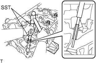
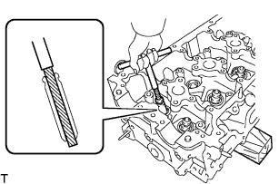
Using SST and a hammer, tap out the guide bush.
- SST
- 09201-01055
- 09950-70010 ( 09951-07100 )
-
Using a caliper gauge, measure the bush bore diameter of the cylinder head.
Standard Bush Bore Diameter Item Specified Condition STD 10.285 to 10.306 mm (0.405 to 0.406 in.) O/S 0.05 10.335 to 10.356 mm (0.407 to 0.408 in.) If the bush bore diameter of the cylinder head is more than 10.306 mm (0.406 in.), machine the bush bore so that the diameter is between 10.335 and 10.356 mm (0.407 and 0.408 in.).
If the bush bore diameter of the cylinder head is more than 10.356 mm (0.408 in.), replace the cylinder head.
-
Select a new valve guide bush.
New Valve Guide Bush Item Specified Condition Bush Bore Diameter 10.333 to 10.344 mm (0.4068 to 0.4072 in.) 10.383 to 10.394 mm (0.4088 to 0.4092 in.) Use Bush STD O/S 0.05 Tech Tips
Standard bush length: 43.0 to 44.0 mm (1.69 to 1.73 in.)
-
Heat the cylinder head to 80 to 100°C (176 to 212°F).
-
Place the cylinder head on wooden blocks.
-
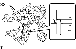
Text in Illustration *1 Height Using SST and a hammer, tap in a new valve guide bush to the specified protrusion height.
- SST
- 09201-01055
- 09950-70010 ( 09951-07100 )
Standard protrusion height 9.8 to 10.2 mm (0.386 to 0.402 in.) -
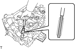
Using a sharp 5.5 mm reamer, ream the valve guide bush to obtain the standard clearance between the guide bush and valve stem.
Standard oil clearance 0.025 to 0.060 mm (0.000984 to 0.00236 in.)
-
-
REPLACE EXHAUST VALVE GUIDE BUSH
-
Heat the cylinder head to 80 to 100°C (176 to 212°F).
-
Place the cylinder head on wooden blocks.
-
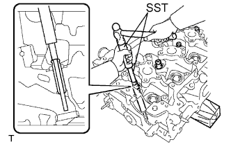
Using SST and a hammer, tap out the guide bush.
- SST
- 09201-01055
- 09950-70010 ( 09951-07100 )
-
Using a caliper gauge, measure the bush bore diameter of the cylinder head.
Standard Bush Bore Diameter Item Specified Condition STD 10.285 to 10.306 mm (0.405 to 0.406 in.) O/S 0.05 10.335 to 10.356 mm (0.407 to 0.408 in.) If the bush bore diameter of the cylinder head is more than 10.306 mm (0.406 in.), machine the bush bore so that the diameter is between 10.335 and 10.356 mm (0.407 and 0.408 in.).
If the bush bore diameter of the cylinder head is more than 10.356 mm (0.408 in.), replace the cylinder head.
-
Select a new valve guide bush.
New Valve Guide Bush Item Specified Condition Bush Bore Diameter 10.333 to 10.344 mm (0.4068 to 0.4072 in.) 10.383 to 10.394 mm (0.4088 to 0.4092 in.) Use Bush STD O/S 0.05 Tech Tips
Standard bush length: 43.0 to 44.0 mm (1.69 to 1.73 in.)
-
Heat the cylinder head to 80 to 100°C (176 to 212°F).
-
Place the cylinder head on wooden blocks.
-
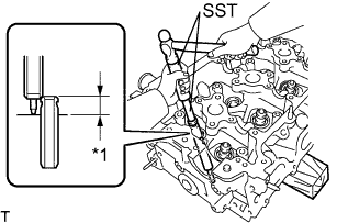
Text in Illustration *1 Height Using SST and a hammer, tap in a new valve guide bush to the specified protrusion height.
- SST
- 09201-01055
- 09950-70010 ( 09951-07100 )
Standard protrusion height 7.6 to 8.0 mm (0.299 to 0.315 in.) -
Using a sharp 5.5 mm reamer, ream the valve guide bush to obtain the standard clearance between the guide bush and valve stem.
Standard oil clearance 0.030 to 0.065 mm (0.00118 to 0.00256 in.)
-
-
REPLACE CAMSHAFT BEARING CAP SETTING RING PIN
Note
It is not necessary to remove a ring pin unless it is being replaced.
-
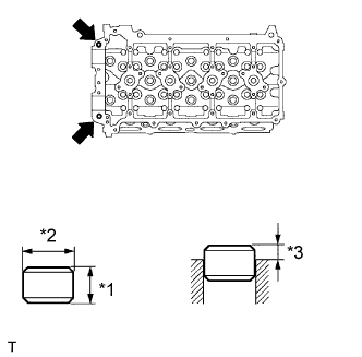
Remove the ring pins.
-
Using a plastic-faced hammer, tap in a new ring pin until the pin stops.
Standard Ring Pin Item Height Width Protrusion Height Ring pin 7 mm (0.276 in.) 10 mm (0.394 in.) 2.5 to 3.8 mm (0.0984 to 0.150 in.) Text in Illustration *1 Height *2 Width *3 Protrusion Height
-
-
REPLACE NO. 1 TIGHT PLUG
Note
If coolant leaks from the tight plug or the plug is corroded, replace it.
-
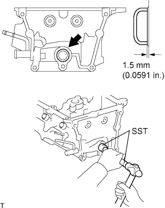
Apply adhesive to the tight plug hole of the cylinder head.
Adhesive Toyota Genuine Adhesive 1324, Three Bond 1324 or equivalent. -
Using SST and a hammer, tap in a new tight plug to the cylinder head as shown in the illustration.
- SST
- 09950-60010 ( 09951-00250 )
- 09950-70010 ( 09951-07100 )
-