ENGINE UNIT INSTALLATION

-
INSTALL FRONT NO. 1 ENGINE MOUNTING BRACKET RH
-
Install the engine mounting bracket with the 4 bolts.
- Torque:
- 51 N*m { 520 kgf*cm, 38 ft.*lbf }
-
-
INSTALL FRONT NO. 1 ENGINE MOUNTING BRACKET LH
-
Install the engine mounting bracket with the 4 bolts.
- Torque:
- 51 N*m { 520 kgf*cm, 38 ft.*lbf }
-
-
INSTALL FRONT ENGINE MOUNTING INSULATOR
-
Install the 2 mounting insulators with the 2 nuts.
- Torque:
- 46 N*m { 469 kgf*cm, 34 ft.*lbf }
-
-
INSTALL ENGINE OIL LEVEL DIPSTICK GUIDE
-
Install the oil level dipstick guide with the bolt.
- Torque:
- 20 N*m { 204 kgf*cm, 15 ft.*lbf }
-
-
INSTALL NO. 1 WATER BY-PASS PIPE
-
Install a new gasket and the water by-pass pipe with the 2 nuts.
- Torque:
- 18 N*m { 178 kgf*cm, 13 ft.*lbf }
-
-
INSTALL NO. 1 IDLER PULLEY SUB-ASSEMBLY
-
Install the spacer and idler pulley with the bolt.
- Torque:
- 43 N*m { 438 kgf*cm, 32 ft.*lbf }
-
-
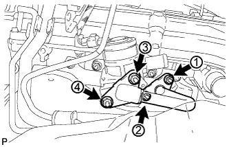
INSTALL NO. 1 COMPRESSOR MOUNTING BRACKET
Note
Install the No. 1 compressor mounting bracket exactly as described in the procedures below to properly secure and prevent damage to the fan and generator V belt.
-
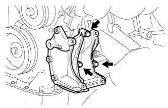
Temporarily install the No. 1 compressor mounting bracket with the 3 bolts.
Tech Tips
Temporarily install the No . 1 compressor mounting bracket with the 3 bolts so that the bracket can be moved by hand.
-
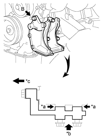
Text in Illustration *a No Clearance *b Push *c Front Push the No. 1 compressor mounting bracket toward the cylinder block as shown in the illustration and tighten bolt B.
- Torque:
- for bolt B
- 45 N*m { 459 kgf*cm, 33 ft.*lbf }
Tech Tips
Make sure there is no clearance between the cylinder block and No. 1 compressor mounting bracket as shown in the illustration.
-
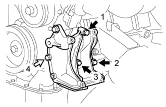
Uniformly tighten the 4 bolts in the order shown in the illustration.
- Torque:
- for bolt A
- 45 N*m { 459 kgf*cm, 33 ft.*lbf }
- for bolt C
- 25 N*m { 250 kgf*cm, 18 ft.*lbf }
Text in Illustration 
Bolt A 
Bolt C
-
-
INSTALL IDLE PULLEY ASSEMBLY
-
Temporarily install the idle pulley assembly with the bolt.
Note
Do not use any tools.
-
Tighten the bolt.
- Torque:
- 44 N*m { 449 kgf*cm, 32 ft.*lbf }
-
-
INSTALL INTAKE MANIFOLD
-
Install the No. 2 fuel vapor feed hose to the intake manifold.
-
Install the 2 wire harness clamp brackets to the intake manifold with the 2 bolts.
- Torque:
- 8.0 N*m { 82 kgf*cm, 71 in.*lbf }
-

Install a new gasket to the intake manifold.
-
Install the intake manifold with the 5 bolts and 2 nuts.
- Torque:
- 25 N*m { 255 kgf*cm, 18 ft.*lbf }
-
for Engine Rear Side:
Attach the No. 2 water by-pass hose and connect the No. 3 ventilation hose to the intake manifold.
-
for Engine Front Side:
Attach the 2 wire harness clamps to the 2 wire harness clamp brackets.
-
-
INSTALL PURGE VSV
-
Install the purge VSV with the bolt.
- Torque:
- 9.0 N*m { 92 kgf*cm, 80 in.*lbf }
-
Connect the 2 purge line hoses to the purge VSV.
-
Connect the purge VSV connector.
-
-
INSTALL FUEL DELIVERY PIPE WITH FUEL INJECTOR
-
Install the fuel delivery pipe with fuel injector Click here.
-
-
INSTALL THROTTLE WITH MOTOR BODY ASSEMBLY
-
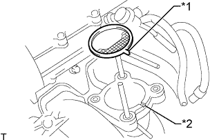
Text in Illustration *1 Protrusion *2 Groove Install a new gasket to the intake manifold.
Tech Tips
Align the protrusion of the gasket with the groove of the intake manifold.
-
for Type A:
Install the throttle body with motor with the 2 bolts and 2 nuts.
- Torque:
- 9.0 N*m { 92 kgf*cm, 80 in.*lbf }
-
for Type B:
Install the throttle body with motor with the 4 bolts.
- Torque:
- 9.0 N*m { 92 kgf*cm, 80 in.*lbf }
-
Connect the water by-pass hose.
-
Connect the No. 2 water by-pass hose.
-
Connect the throttle position sensor and throttle control motor connector.
-
-
INSTALL EXHAUST MANIFOLD
-
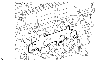
Install a new gasket.
-
Install the exhaust manifold with 8 new nuts in the order shown in the illustration.
- Torque:
- 36 N*m { 367 kgf*cm, 27 ft.*lbf }
-
-
INSTALL AIR SWITCHING VALVE ASSEMBLY
-
Set the No. 1 exhaust manifold heat insulator in place.
-
Install the air switching valve with 2 new nuts.
- Torque:
- 20 N*m { 204 kgf*cm, 15 ft.*lbf }
-
Connect the connector.
-
w/ Manifold Absolute Pressure Sensor:
Connect the vacuum hose.
-
-
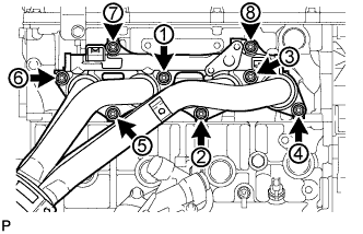
INSTALL NO. 4 INTAKE PIPE
-
Install 2 new gaskets and the No. 4 intake pipe with 4 new nuts in the order shown in the illustration. Tighten the nuts labeled 1 and 3 to the torque specification again.
- Torque:
- 20 N*m { 204 kgf*cm, 15 ft.*lbf }
-
Check that the nuts are tightened to the torque specification.
-
-
INSTALL NO. 1 EXHAUST MANIFOLD HEAT INSULATOR
-
Install the No. 1 exhaust manifold heat insulator with the 5 bolts.
- Torque:
- 12 N*m { 122 kgf*cm, 9 ft.*lbf }
-
-
INSTALL GENERATOR ASSEMBLY
-
for 80 A Type:
Install the generator Click here.
-
for 100 A Type:
Install the generator Click here.
-
-
INSTALL IGNITION COIL ASSEMBLY
-
Install the 4 ignition coils with the 4 bolts.
- Torque:
- 9.0 N*m { 92 kgf*cm, 80 in.*lbf }
-
Connect the 4 ignition coil connectors.
-