ENGINE UNIT REASSEMBLY

-
INSTALL CRANKSHAFT PULLEY SET KEY
-
Install the 2 pulley keys to the crankshaft.
-
-
INSTALL NO. 4 CHAIN VIBRATION DAMPER
-
Install the vibration damper with the 2 bolts.
- Torque:
- 18 N*m { 184 kgf*cm, 13 ft.*lbf }
-
-
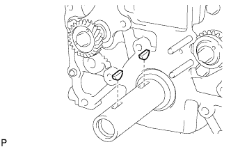
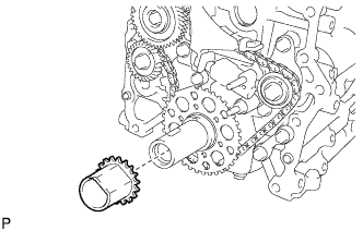
INSTALL NO. 2 CHAIN SUB-ASSEMBLY
-
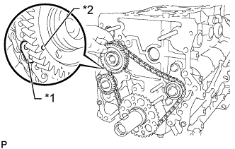
Install the timing sprocket as shown in the illustration.
Note
Check that the No. 1 cylinder is at TDC and that the weights of the No. 1 and No. 2 balance shafts are at the bottom.
Tech Tips
Install the timing sprocket with the front mark facing forward.
-
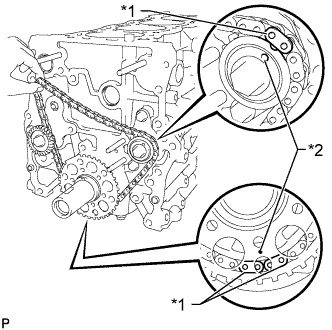
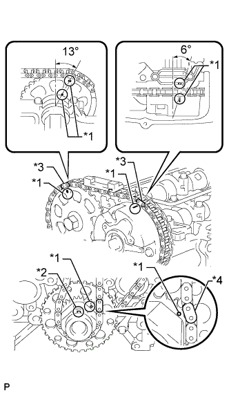
Text in Illustration *1 Mark Plate (Yellow) *2 Timing Mark As shown in the illustration, install the chain to the sprocket and gear with the mark plates aligned with the timing marks on the sprocket and gear.
-
Text in Illustration *1 Mark Plate (Yellow) *2 Large Timing Mark Fit the other mark link of the chain behind the large timing mark of the balance shaft drive gear.
-
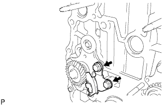
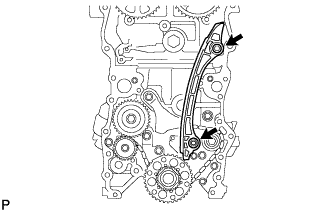
Insert the balance shaft drive gear shaft through the balance shaft drive gear so that it fits into the thrust plate hole.
-
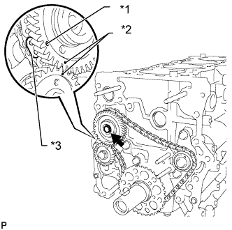
Text in Illustration *1 Large Timing Mark *2 Small Timing Mark *3 Mark Plate (Yellow) Align the small timing mark of the balance shaft drive gear with the large timing mark of the balance shaft timing gear.
-
Install the bolt to the balance shaft drive gear.
- Torque:
- 25 N*m { 255 kgf*cm, 18 ft.*lbf }
-
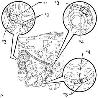
Text in Illustration *1 Large Timing Mark *2 Small Timing Mark *3 Mark Plate (Yellow) *4 Timing Mark Check that each timing mark is aligned with the corresponding mark link.
Note
Check that the No. 1 cylinder is at TDC and that the weights of the No. 1 and No. 2 balance shafts are at the bottom.
-
-
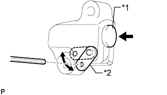
INSTALL NO. 2 CHAIN TENSIONER ASSEMBLY
-
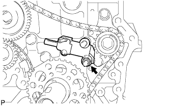
Install the chain tensioner assembly with the nut.
- Torque:
- 18 N*m { 184 kgf*cm, 13 ft.*lbf }
Note
Install the chain tensioner with the pin installed, and then remove the pin after installation. When performing this step, do not push the vibration damper against the chain.
-
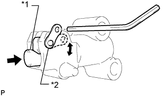
Text in Illustration *1 Plunger *2 Stopper Plate Move the stopper plate downward to release the lock and push the plunger deep into the tensioner.
-
Move the stopper plate upward to set the lock and insert a hexagon wrench into the stopper plate hole.
-
-
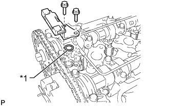
INSTALL NO. 3 CHAIN VIBRATION DAMPER
-
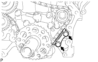
Install the chain vibration damper with the 2 bolts.
- Torque:
- 18 N*m { 184 kgf*cm, 13 ft.*lbf }
-
-
INSTALL NO. 2 CHAIN VIBRATION DAMPER
-
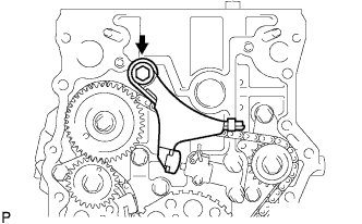
Install the chain vibration damper with the bolt.
- Torque:
- 27 N*m { 270 kgf*cm, 20 ft.*lbf }
-
Remove the pin from the chain tensioner assembly and release the plunger.
-
-
INSTALL NO. 1 TAPER SCREW PLUG
-
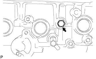
Install the screw plug to the cylinder block.
- Torque:
- 25 N*m { 250 kgf*cm, 18 ft.*lbf }
-
-
INSTALL OIL FILTER BRACKET SUB-ASSEMBLY
-
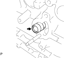
Using a hexagon wrench, install the oil filter bracket union.
- Torque:
- 25 N*m { 250 kgf*cm, 18 ft.*lbf }
-
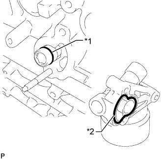
Text in Illustration *1 O-Ring *2 Oil Filter Bracket Gasket Install a new oil filter bracket gasket to the oil filter bracket.
-
Install a new O-ring to the oil filter bracket union.
Note
Apply a light coat of engine oil to the O-ring and oil filter bracket.
-
Install 2 new gaskets and the 2 screw plugs to the oil filter bracket.
- Torque:
- 49 N*m { 500 kgf*cm, 36 ft.*lbf }
-

Install the oil filter bracket with the 2 bolts and nut.
- Torque:
- 25 N*m { 255 kgf*cm, 18 ft.*lbf }
-
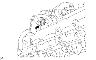
Using a 27 mm socket wrench, install the oil filter union.
- Torque:
- 43 N*m { 439 kgf*cm, 32 ft.*lbf }
-
-
INSTALL OIL FILTER SUB-ASSEMBLY
-
Check and clean the oil filter installation surface.
-
Apply clean engine oil to the gasket of a new oil filter.
-
Lightly screw the oil filter into place by hand. Tighten it until the gasket contacts the seat.
-
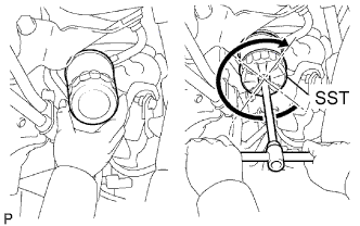
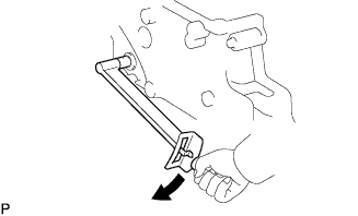
Using SST, tighten the oil filter.
- SST
- 09228-07501
-
Depending on the work space available, choose from the following.
If enough space is available, use a torque wrench to tighten the oil filter.
- Torque:
- 17 N*m { 175 kgf*cm, 13 ft.*lbf }
If enough space is not available to use a torque wrench, tighten the oil filter a 3/4 turn by hand or use a common wrench.
-
-
INSTALL ENGINE REAR OIL SEAL
-
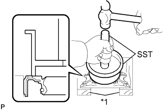
Text in Illustration *1 Wooden Block Place the oil seal retainer on wooden blocks.
-
Apply a light coat of MP grease to the lip of a new oil seal.
Note
-
Do not allow foreign matter to contact the lip of the oil seal.
-
Do not allow MP grease to contact the dust seal.
-
-
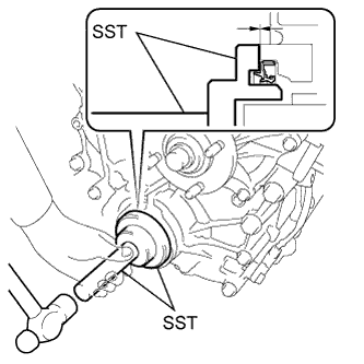
Using SST, tap in a new oil seal until its surface is flush with the oil seal retainer edge.
- SST
- 09223-15030
- 09950-70010 ( 09951-07150 )
Note
-
Wipe off any extra grease from the crankshaft.
-
Do not tap in the oil seal at an angle.
-
-
INSTALL ENGINE REAR OIL SEAL RETAINER
-
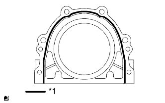
Text in Illustration *1 Seal Packing Apply seal packing in a continuous bead as shown in the illustration.
Seal packing Toyota Genuine Seal Packing Black, Three Bond 1207B or equivalent Seal width 2.0 to 3.0 mm (0.079 to 0.118 in.) Note
-
Remove any oil from the contact surface.
-
Install the rear oil seal retainer within 3 minutes after applying seal packing.
-
Do not start the engine for at least 4 hours after installation.
-
-
Install the oil seal retainer with the 6 bolts.
- Torque:
- 13 N*m { 133 kgf*cm, 10 ft.*lbf }
-
-
INSTALL OIL CONTROL VALVE FILTER
-
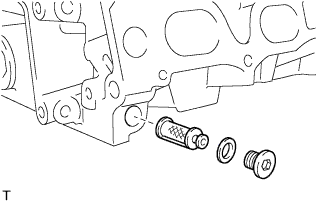
Check that no foreign matter is on the mesh part of the filter.
If foreign matter is present, clean the part thoroughly.
-
Using an 8 mm hexagon wrench, install a new gasket and the oil control valve filter with the screw plug.
- Torque:
- 30 N*m { 306 kgf*cm, 22 ft.*lbf }
-
-
INSTALL CYLINDER HEAD GASKET
-
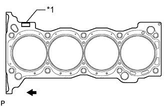
Text in Illustration *1 Lot No. 
Front Place a new cylinder head gasket on the cylinder block surface with the lot No. stamp facing upward.
Note
Make sure that the cylinder head gasket is installed so that it is facing in the correct direction.
-
-
INSTALL CYLINDER HEAD SUB-ASSEMBLY
Tech Tips
The cylinder head bolts are tightened in 3 successive steps.
-
Place the cylinder head on the cylinder block.
Note
-
Make sure that no oil is on the mounting surface of the cylinder head.
-
Place the cylinder head on the cylinder block gently in order not to damage the gasket with the bottom part of the head.
-
-
Install the plate washers to the cylinder head bolts.
-
Apply a light coat of engine oil to the threads and under the heads of the cylinder head bolts.
-
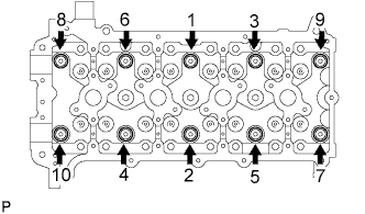
Step 1:
Using several steps, install and uniformly tighten the 10 cylinder head bolts with plate washers in the sequence shown in the illustration.
- Torque:
- 39 N*m { 398 kgf*cm, 29 ft.*lbf }
-
Mark the front of each cylinder head bolt head with paint.
-
Step 2:
Tighten the cylinder head bolts 90° in the sequence shown in step 1.
-
Step 3:
Tighten the cylinder head bolts another 90° in the sequence shown in step 1.
-
Check that the paint marks are now at a 180° angle to the front.
-
-
INSTALL CAMSHAFT TIMING SPROCKET
-
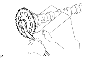
Mount the camshaft in a vise and install the camshaft timing sprocket to the camshaft with the sprocket bolt.
- Torque:
- 78 N*m { 795 kgf*cm, 58 ft.*lbf }
Note
Do not damage the camshaft in the vise.
-
-
INSTALL CAMSHAFT TIMING GEAR ASSEMBLY
-
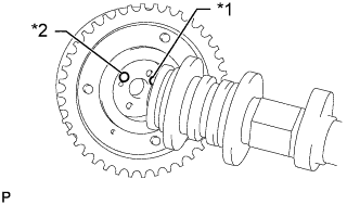
Text in Illustration *1 Straight Pin *2 Pin Hole Align the pin hole and straight pin and install the camshaft timing gear to the camshaft.
-
Lightly press the gear against the camshaft and turn the gear. Push further at the position where the pin enters the groove.
-
Check that there is no gap between the flange of the gear and the camshaft.
-
With the camshaft timing gear fixed in place, install the flange bolt.
- Torque:
- 78 N*m { 795 kgf*cm, 58 ft.*lbf }
-
Check that the camshaft timing gear can move in the retard direction and becomes locked at the most retarded position.
-
-
INSTALL VALVE LASH ADJUSTER ASSEMBLY
-
Inspect each valve lash adjuster before installing it Click here.
-
Install the 16 valve lash adjusters to the cylinder head.
Note
Install each lash adjuster to the same place it was removed from.
-
-
INSTALL VALVE STEM CAP
-
Apply a light coat of engine oil to the valve stem ends.
-
Install the 16 valve stem caps to the cylinder head.
Note
Do not drop the valve stem caps into the cylinder head.
-
-
INSTALL NO. 1 VALVE ROCKER ARM SUB-ASSEMBLY
-
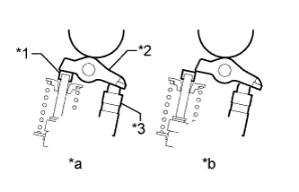
Text in Illustration *1 Valve Stem Cap *2 Valve Rocker Arm *3 Valve Lash Adjuster *a CORRECT *b INCORRECT Apply clean engine oil to the valve lash adjuster tips and valve stem cap surfaces.
-
Install the 16 valve rocker arms as shown in the illustration.
Note
Install each valve rocker arm to the same place it was removed from.
-
-
INSTALL CAMSHAFT
-
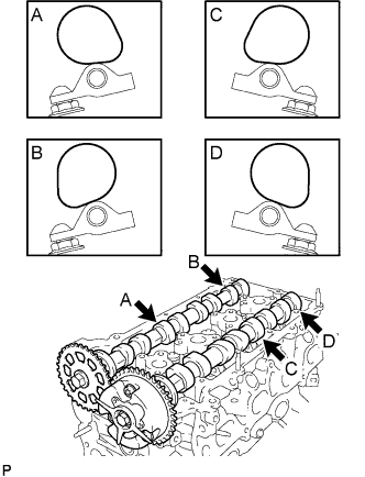
Apply clean engine oil to the camshaft cams and cylinder head journals.
-
Position the camshaft and No. 2 camshaft as shown in the illustration.
-
-
INSTALL CAMSHAFT BEARING CAP
-
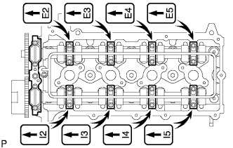
Temporarily install the No. 1 camshaft bearing cap.
-
Check the proper location of each No. 2 camshaft bearing cap and install them.
-
Text in Illustration *1 O-Ring Install a new O-ring to the No. 1 camshaft bearing cap.
-
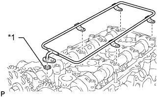
Temporarily install the oil delivery pipe.
-
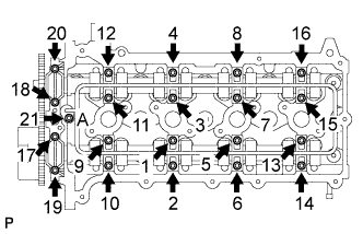
Install the 21 bolts and tighten them in the order shown in the illustration.
- Torque:
- for bolt A
- 12 N*m { 122 kgf*cm, 9 ft.*lbf }
- except bolt A
- 16 N*m { 158 kgf*cm, 11 ft.*lbf }
-
-
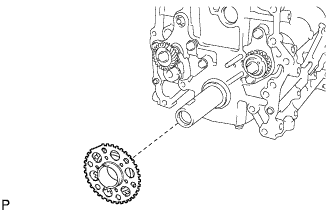
INSTALL CRANKSHAFT TIMING GEAR
-
Install the timing gear as shown in the illustration.
-
-
INSTALL NO. 1 CHAIN VIBRATION DAMPER
-
Install the vibration damper with the bolt and nut.
- Torque:
- for bolt
- 21 N*m { 214 kgf*cm, 15 ft.*lbf }
- for nut
- 18 N*m { 184 kgf*cm, 13 ft.*lbf }
-
-
INSTALL CHAIN SUB-ASSEMBLY
-
Text in Illustration *1 Timing Mark *2 Key *3 Mark Plate (Orange) *4 Mark Plate (Yellow) As shown in the illustration, install the chain to the sprocket and gear with the mark plates aligned with the timing marks on the sprocket and gear.
Tech Tips
-
The camshaft mark plate is orange.
-
The crankshaft mark plate is yellow.
-
-
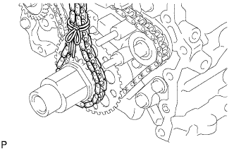
Use a rope to secure the chain of the crankshaft timing sprocket. Tie the rope near the sprocket.
Note
After the chain tensioner has been installed, the rope must be removed.
Tech Tips
The rope is used to prevent the chain from jumping a tooth.
-
-
INSTALL CHAIN TENSIONER SLIPPER
-
Install the tensioner slipper with the bolt.
- Torque:
- 21 N*m { 214 kgf*cm, 15 ft.*lbf }
-
-
INSTALL NO. 1 CHAIN TENSIONER ASSEMBLY
-
Text in Illustration *1 Plunger *2 Stopper Plate Move the stopper plate upward to release the lock and push the plunger deep into the tensioner.
-
Move the stopper plate downward to set the lock and insert a hexagon wrench into the hole of the stopper plate.
-
Install a new gasket and the chain tensioner with the bolt and nut.
- Torque:
- 10 N*m { 102 kgf*cm, 7 ft.*lbf }
-
-
INSTALL TIMING CHAIN GUIDE
-
Text in Illustration *1 O-Ring Install a new O-ring to the camshaft bearing cap.
-
Install the timing chain guide with the 2 bolts.
- Torque:
- 10 N*m { 102 kgf*cm, 7 ft.*lbf }
-
-
INSTALL WATER PUMP ASSEMBLY
-
Install a new gasket and the water pump with the 8 bolts.
- Torque:
- 9.0 N*m { 91 kgf*cm, 79 in.*lbf }
-
-
INSTALL OIL PUMP RELIEF VALVE
-
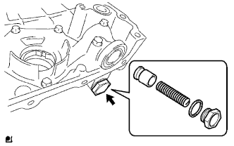
Coat the relief valve with engine oil.
-
Insert the relief valve and spring into the pump body hole.
-
Install a new gasket to the plug.
-
Using a 27 mm socket wrench, install the plug.
- Torque:
- 49 N*m { 500 kgf*cm, 36 ft.*lbf }
-
-
INSTALL TIMING CHAIN COVER SUB-ASSEMBLY
-
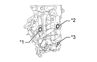
Text in Illustration *1 New Water Pump O-ring *2 New Water Pump Upper O-ring *3 New Oil Pump O-ring Install 3 new O-rings to the timing chain cover as shown in the illustration.
-
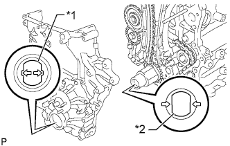
Text in Illustration *1 Drive Rotor Spline *2 Crankshaft Timing Gear Align the drive rotor spline of the oil pump and crankshaft timing gear as shown in the illustration.
-
Apply seal packing to the timing chain cover in a continuous line as shown in the following illustration.
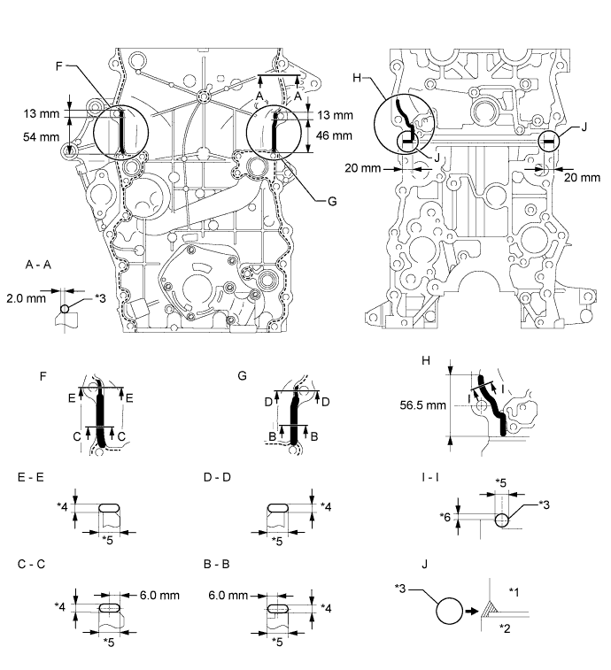
Seal packing Toyota Genuine Seal Packing Black, Three Bond 1207B or equivalent Application Specification Area Seal Packing Diameter Distance from Edge of Cover to Center of Seal Packing Seal Packing Application Length Protrusion from Cylinder Head A - A
(Dashed line)
2.5 to 4.0 mm (0.0984 to 0.157 in.) 2.0 mm (0.0787 in.) - - B - B
(Continuous line)
10 to 14 mm (0.394 to 0.551 in.) wide and 2.5 to 4.0 mm (0.0984 to 0.157 in.) thick 6.0 mm (0.236 in.) 46 mm (1.81 in.) from top of bolt hole - C - C
(Continuous line)
10 to 14 mm (0.394 to 0.551 in.) wide and 2.5 to 4.0 mm (0.0984 to 0.157 in.) thick 6.0 mm (0.236 in.) 54 mm (2.13 in.) from top of bolt hole - D - D
(Continuous line)
9.0 to 13 mm (0.354 to 0.512 in.) wide and 2.5 to 4.0 mm (0.0984 to 0.157 in.) thick - 13 mm (0.512 in.) from top of bolt hole - E - E
(Continuous line)
9.0 to 13 mm (0.354 to 0.512 in.) wide and 2.5 to 4.0 mm (0.0984 to 0.157 in.) thick - 13 mm (0.512 in.) from top of bolt hole - I - I
(Continuous line)
8.0 mm (0.315 in.) - 56.5 mm (2.22 in.) from bottom of cylinder head 2.0 to 3.0 mm (0.0787 to 0.118 in.) J 10 mm (0.394 in.) - 20 mm (0.787 in.) - Text in Illustration *1 Cylinder Head *2 Cylinder Block *3 Seal Packing *4 Seal Packing Thickness *5 Seal Packing Width *6 Protrusion Note
-
Remove any oil from the contact surface.
-
When the contact surfaces are wet, wipe them with an oil-free cloth before applying seal packing.
-
Install the timing chain cover within 3 minutes and tighten the bolts within 15 minutes after applying seal packing.
-
Do not start the engine for at least 4 hours after the installation.
-
-
Temporarily install the timing chain cover with the 19 bolts and 2 nuts.
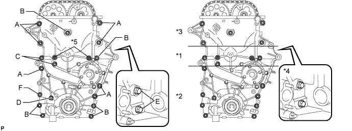
Bolt Length Item Length Thread Diameter Bolt A 75 mm (2.95 in.) 10 mm (0.394 in.) Bolt B 75 mm (2.95 in.) 8 mm (0.315 in.) Bolt C 90 mm (3.54 in.) 8 mm (0.315 in.) Bolt D 95 mm (3.74 in.) 8 mm (0.315 in.) Bolt E 35 mm (1.38 in.) 8 mm (0.315 in.) Bolt F 75 mm (2.95 in.) 10 mm (0.394 in.) -
Excluding the bolts labeled A and F, tighten the bolts and nuts in this order: Area 1, Area 3, Area 2.
- Torque:
- for bolt C
- 26 N*m { 265 kgf*cm, 19 ft.*lbf }
- for bolt B, D and nut
- 21 N*m { 214 kgf*cm, 15 ft.*lbf }
Text in Illustration *1 Area 1 *2 Area 2 *3 Area 3 *4 Area 4 *5 Nut - - -
Tighten the bolts labeled A in this order: Area 2 and Area 3.
- Torque:
- 60 N*m { 612 kgf*cm, 44 ft.*lbf }
-
Tighten the bolts labeled F.
- Torque:
- 46 N*m { 469 kgf*cm, 34 ft.*lbf }
-
Tighten the bolts labeled E in Area 4.
- Torque:
- 21 N*m { 214 kgf*cm, 15 ft.*lbf }
-
-
INSTALL V-RIBBED BELT TENSIONER ASSEMBLY
-
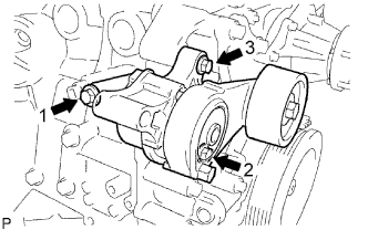
Temporarily install the belt tensioner with the 3 bolts.
Tech Tips
Make sure that the flanges of the bolts are contacting the tensioner surface.
-
Install the tensioner by tightening the 3 bolts in the order shown in the illustration.
- Torque:
- for bolt 1
- 40 N*m { 408 kgf*cm, 30 ft.*lbf }
- for bolt 2
- 21 N*m { 214 kgf*cm, 15 ft.*lbf }
- for bolt 3
- 43 N*m { 438 kgf*cm, 32 ft.*lbf }
-
-
INSTALL STRAIGHT SCREW PLUG
-
Apply adhesive to the straight screw plug.
Adhesive Toyota Genuine Adhesive 1324, Three Bond 1324 or equivalent -
Using a 10 mm socket hexagon wrench, install the straight screw plug.
- Torque:
- 17 N*m { 169 kgf*cm, 12 ft.*lbf }
-
-
INSTALL TIMING CHAIN COVER OIL SEAL
-
Apply MP grease to the lip of a new oil seal.
Note
-
Do not allow foreign matter to contact the lip of the oil seal.
-
Do not allow MP grease to contact the dust seal.
-
-
Temporarily install the oil seal to the timing chain cover.
-
Using SST and a hammer, tap in the oil seal until its surface is flush with the chain cover edge.
- SST
- 09223-75010
- 09950-70010 ( 09951-07100 )
Note
-
Keep the lip free from foreign matter.
-
Do not tap the oil seal at an angle.
-
-
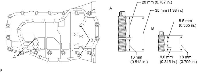
INSTALL OIL PAN STUD BOLT
Note
If a stud bolt is deformed or threads are damaged, replace it.
-
Using E5 and E8 "TORX" socket wrenches, install the stud bolts.
- Torque:
- for stud bolt A
- 7.5 N*m { 76 kgf*cm, 66 in.*lbf }
- for stud bolt B
- 3.0 N*m { 31 kgf*cm, 27 in.*lbf }
-
-
INSTALL OIL PAN SUB-ASSEMBLY
-
Install a new O-ring.
-
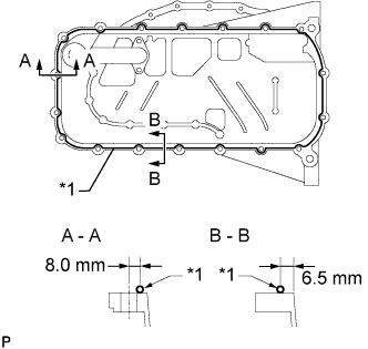
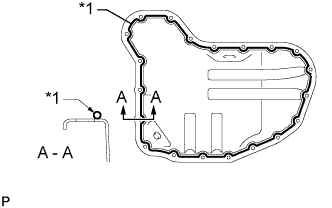
Text in Illustration *1 Seal Packing Apply seal packing in a continuous line as shown in the illustration.
Seal packing Toyota Genuine Seal Packing Black, Three Bond 1207B or equivalent Application Specification Area Seal Packing Diameter Distance from Edge of Cover or Center of Bolt Hole to Center of Seal Packing A - A 2.0 to 3.0 mm (0.0787 to 0.118 in.) 8.0 mm (0.315 in.) B - B 2.0 to 3.0 mm (0.0787 to 0.118 in.) 6.5 mm (0.256 in.) Note
-
Remove any oil from the contact surface.
-
Install the oil pan within 3 minutes after applying seal packing.
-
Do not start the engine for at least 4 hours after the installation.
-
-
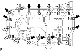
Temporarily install the oil pan with the 16 bolts and 2 nuts.
Bolt Length Item Length Bolt A 20 mm (0.787 in.) Bolt B 40 mm (1.57 in.) Text in Illustration Bolt A 
Bolt B 
Nut -
Uniformly tighten the 16 bolts and 2 nuts in the order shown in the illustration.
- Torque:
- 26 N*m { 265 kgf*cm, 19 ft.*lbf }
-
-
INSTALL OIL STRAINER SUB-ASSEMBLY
-
Install a new gasket and the oil strainer with the bolt and 2 nuts.
- Torque:
- 26 N*m { 265 kgf*cm, 19 ft.*lbf }
-
-
INSTALL NO. 2 OIL PAN SUB-ASSEMBLY
-
Text in Illustration *1 Seal Packing Apply seal packing in a continuous line as shown in the illustration.
Seal packing Toyota Genuine Seal Packing Black, Three Bond 1207B or equivalent Seal packing diameter 3.0 to 4.0 mm (0.118 to 0.157 in.) Note
-
Remove any oil from the contact surface.
-
Install the oil pan within 3 minutes after applying seal packing.
-
Do not start the engine for at least 4 hours after the installation.
-
-
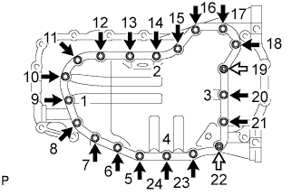
Temporarily install the oil pan with the 20 bolts and 2 nuts.
Text in Illustration Bolt Nut -
Uniformly tighten the 20 bolts and 2 nuts in the order shown in the illustration.
- Torque:
- 9.0 N*m { 92 kgf*cm, 80 in.*lbf }
-
Install a new gasket and the drain plug.
- Torque:
- 38 N*m { 382 kgf*cm, 28 ft.*lbf }
-
-
INSTALL CRANKSHAFT PULLEY
-
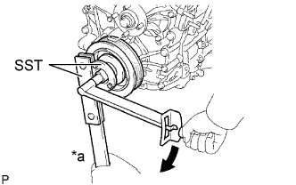
Text in Illustration *a Hold Turn Align the key groove of the pulley with the pulley set key and slide on the pulley.
-
Using SST, install a new crankshaft pulley bolt.
- SST
- 09213-54015 ( 91651-60855 )
- 09330-00021
- Torque:
- 260 N*m { 2651 kgf*cm, 192 ft.*lbf }
Note
Do not reuse the pulley bolt.
-
-
INSTALL CYLINDER HEAD COVER SUB-ASSEMBLY
-
Install 2 new cover gaskets to the head cover.
-
Apply seal packing to the places shown in the illustration.
Seal packing Toyota Genuine Seal Packing Black, Three Bond 1207B or equivalent Seal packing diameter 4.0 mm (0.157 in.) Text in Illustration Seal Packing Note
-
Remove any oil from the contact surface.
-
Install the head cover within 3 minutes after applying seal packing.
-
Do not start the engine for at least 4 hours after the installation.
-
-
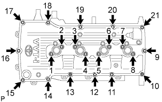
Temporarily install the head cover with the 19 bolts and 2 nuts.
-
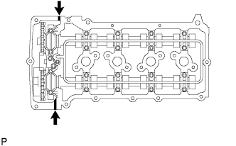
Uniformly tighten the 19 bolts and 2 nuts in the order shown in the illustration.
- Torque:
- 9.0 N*m { 92 kgf*cm, 80 in.*lbf }
-
In numerical order, confirm that the bolts labeled 1 to 8 are tightened to the specified torque. Tighten the bolts as necessary.
-
-
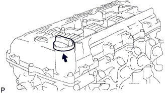
INSTALL THERMOSTAT
-
Install a new gasket to the thermostat.
-
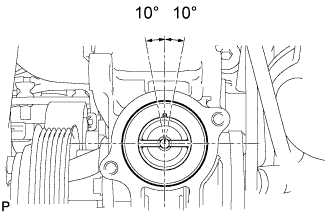
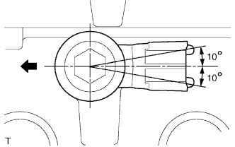
Install the thermostat with the jiggle valve upward.
Tech Tips
The jiggle valve may be set within 10° to either side of the prescribed position.
-
-
INSTALL WATER INLET
-
Install a new gasket and water inlet with the 2 nuts and bolt.
- Torque:
- 28 N*m { 286 kgf*cm, 21 ft.*lbf }
-
-
INSTALL CAMSHAFT TIMING OIL CONTROL VALVE ASSEMBLY
-
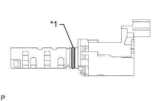
Text in Illustration *1 New O-Ring Install a new O-ring to the oil control valve.
-
Apply a light coat of engine oil to the O-ring.
-
Install the camshaft timing oil control valve with the bolt.
- Torque:
- 8.0 N*m { 82 kgf*cm, 71 in.*lbf }
-
Connect the camshaft timing oil control valve connector.
-
Install the wiring harness clamp bracket with the bolt.
- Torque:
- 8.0 N*m { 82 kgf*cm, 71 in.*lbf }
-
Attach the 2 clamps and connect the 2 connectors.
-
-
INSTALL CRANKSHAFT POSITION SENSOR
-
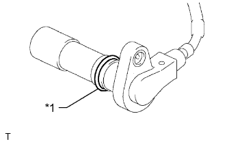
Text in Illustration *1 O-Ring Apply a light coat of engine oil to the O-ring of the crankshaft position sensor.
-
Install the crankshaft position sensor with the bolt.
- Torque:
- 8.5 N*m { 87 kgf*cm, 75 in.*lbf }
Note
Make sure that the O-ring is not cracked or jammed when installing.
-
Connect the crankshaft position sensor connector and attach the wire harness clamp.
-
-
INSTALL CAMSHAFT POSITION SENSOR
-
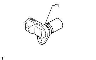
Text in Illustration *1 O-Ring Apply a light coat of engine oil to the O-ring of the camshaft position sensor.
-
Install the camshaft position sensor with the bolt.
- Torque:
- 8.5 N*m { 87 kgf*cm, 75 in.*lbf }
Note
Make sure that the O-ring is not cracked or jammed when installing.
-
Connect the camshaft position sensor connector.
-
-
INSTALL PCV VALVE SUB-ASSEMBLY
-
Apply adhesive to 2 or 3 threads of the valve.
Adhesive Toyota genuine adhesive 1324, three bond 1324 or equivalent -
Using a 22 mm ball joint lock nut wrench, install the PCV valve.
- Torque:
- 5.0 N*m { 51 kgf*cm, 44 in.*lbf }
Note
Use the formula to calculate special torque values for situations where a ball joint lock nut wrench is combined with a torque wrench Click here.
-
Connect the PCV hose.
-
-
INSTALL OIL FILLER CAP SUB-ASSEMBLY
-
Install the gasket to the oil filler cap.
-
Install the oil filler cap.
-
-
INSTALL ENGINE COOLANT TEMPERATURE SENSOR
-
Install a new gasket to the engine coolant temperature sensor.
-
Using a 19 mm deep socket wrench, install the engine coolant temperature sensor.
- Torque:
- 20 N*m { 200 kgf*cm, 14 ft.*lbf }
-
Connect the engine coolant temperature sensor connector.
-
-
INSTALL KNOCK SENSOR
-
Install the knock sensor with the bolt.
Text in Illustration Front - Torque:
- 20 N*m { 204 kgf*cm, 15 ft.*lbf }
Note
Make sure that the knock sensor is at the correct angle when installing.
-
Connect the knock sensor connector.
-
-
INSTALL ENGINE OIL PRESSURE SWITCH ASSEMBLY
-
Apply adhesive to 2 or 3 threads of the oil pressure switch.
Adhesive TOYOTA Genuine Adhesive 1344, Three Bond 1344 or equivalent Note
Do not let adhesive adhere to the oil hole.
-
Using a 24 mm deep socket wrench, install the oil pressure switch.
- Torque:
- 15 N*m { 153 kgf*cm, 11 ft.*lbf }
Note
Do not start the engine within 1 hour of installation.
-
Connect the oil pressure switch connector.
-
-
INSTALL SPARK PLUG
-
Using a 16 mm spark plug wrench, install the 4 spark plugs.
- Torque:
- 18 N*m { 184 kgf*cm, 13 ft.*lbf }
-