ENGINE UNIT DISASSEMBLY

-
REMOVE SPARK PLUG
-
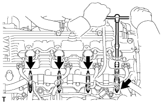
Using a 16 mm spark plug wrench, remove the 4 spark plugs.
-
-
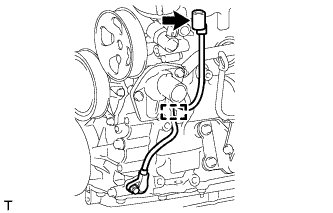
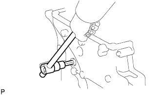
REMOVE ENGINE OIL PRESSURE SWITCH ASSEMBLY
-
Disconnect the oil pressure switch connector.
-
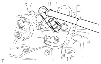
Using a 24 mm deep socket wrench, remove the oil pressure switch.
-
-
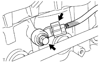
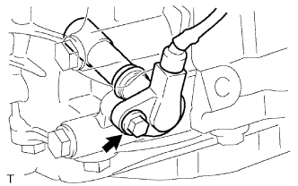
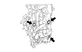
REMOVE KNOCK SENSOR
-
Disconnect the knock sensor connector.
-
Remove the bolt and knock sensor.
-
-
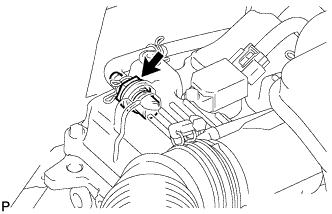
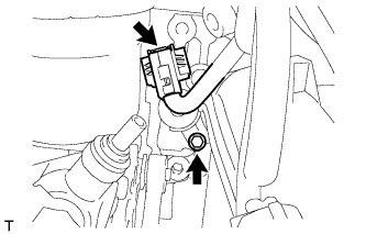
REMOVE ENGINE COOLANT TEMPERATURE SENSOR
-
Disconnect the engine coolant temperature sensor connector.
-
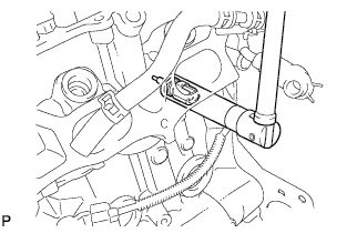
Using a 19 mm deep socket wrench, remove the engine coolant temperature sensor and gasket.
-
-
REMOVE OIL FILLER CAP SUB-ASSEMBLY
-
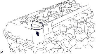
Remove the oil filler cap.
-
Remove the gasket from the oil filler cap.
-
-
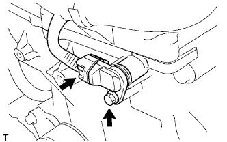
REMOVE PCV VALVE SUB-ASSEMBLY
-
Disconnect the PCV hose from the PCV valve.
-
Using a 22 mm ball joint lock nut wrench, remove the PCV valve.
-
-
REMOVE CAMSHAFT POSITION SENSOR
-
Disconnect the camshaft position sensor connector.
-
Remove the bolt and camshaft position sensor.
-
-
REMOVE CRANKSHAFT POSITION SENSOR
-
Disconnect the crankshaft position sensor connector and detach the wire harness clamp.
-
Remove the bolt and crankshaft position sensor.
-
-
REMOVE CAMSHAFT TIMING OIL CONTROL VALVE ASSEMBLY
-
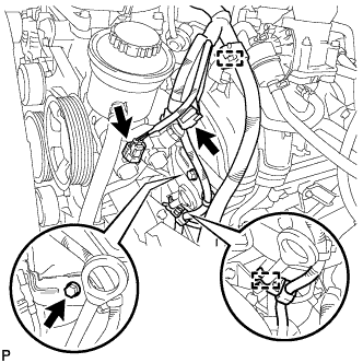
Detach the 2 clamps and disconnect the 2 connectors.
-
Remove the bolt and wiring harness clamp bracket.
-
Disconnect the camshaft timing oil control valve connector.
-
Remove the bolt and camshaft timing oil control valve.
-
Remove the O-ring from the camshaft timing oil control valve.
-
-
REMOVE CYLINDER HEAD COVER SUB-ASSEMBLY
-
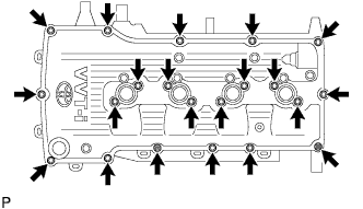
Remove the 19 bolts, 2 nuts, head cover and 2 gaskets.
-
-
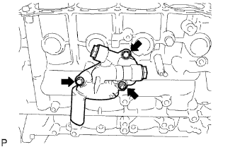
REMOVE WATER INLET
-
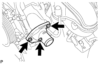
Remove the bolt, 2 nuts, water inlet and gasket.
-
-
REMOVE THERMOSTAT
-
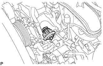
Remove the thermostat from the timing chain cover.
-
-
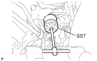
REMOVE CRANKSHAFT PULLEY
-
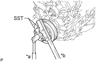
Text in Illustration *a Loosen *b Hold Using SST, hold the crankshaft pulley and loosen the pulley bolt until 2 or 3 threads are screwed into the crankshaft.
- SST
- 09213-54015 ( 91651-60855 )
- 09330-00021
-
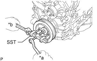
Text in Illustration *a Loosen *b Hold Using SST and the pulley bolt, remove the crankshaft pulley.
- SST
- 09950-50013 ( 09951-05010, 09952-05010, 09953-05010, 09954-05021 )
Tech Tips
Apply lubricant to the threads and end of SST.
-
-
REMOVE NO. 2 OIL PAN SUB-ASSEMBLY
-
Remove the drain plug and gasket.
-
Remove the 18 bolts and 2 nuts.
-
Insert the blade of an oil pan seal cutter between the oil pans. Cut through the applied sealer and remove the oil pan.
Note
Be careful not to damage the contact surfaces of the oil pans.
-
-
REMOVE OIL STRAINER SUB-ASSEMBLY
-
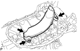
Remove the bolt, 2 nuts, oil strainer and gasket.
-
-
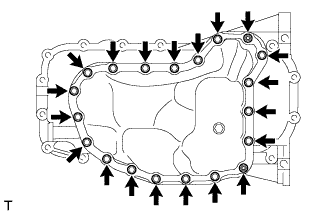
REMOVE OIL PAN SUB-ASSEMBLY
-

Remove the 16 bolts and 2 nuts.
-
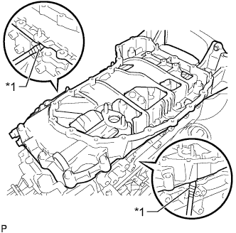
Text in Illustration *1 Protective Tape Remove the oil pan by prying between the oil pan and cylinder block with a screwdriver.
Tech Tips
Tape the screwdriver tip before use.
Note
Be careful not to damage the contact surfaces of the cylinder block and oil pan.
-
Remove the O-ring.
-
-
REMOVE OIL PAN STUD BOLT
Note
If a stud bolt is deformed or its threads are damaged, replace it.
-
REMOVE V-RIBBED BELT TENSIONER ASSEMBLY
-
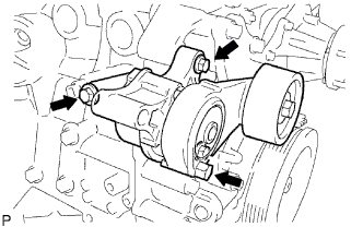
Remove the 3 bolts and belt tensioner.
-
-
REMOVE TIMING CHAIN COVER SUB-ASSEMBLY
-
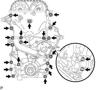
Remove the 19 bolts and 2 nuts shown in the illustration.
-
Text in Illustration *1 Protective Tape Remove the timing chain cover by prying between the timing chain cover and cylinder head or cylinder block with a screwdriver.
Tech Tips
Tape the screwdriver tip before use.
Note
Be careful not to damage the contact surfaces of the cylinder head, cylinder block and timing chain cover.
-
Remove the 3 O-rings.
-
-
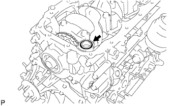
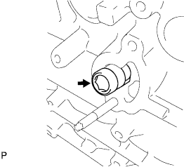
REMOVE STRAIGHT SCREW PLUG
-
Using a 10 mm socket hexagon wrench, remove the straight screw plug.
-
-
REMOVE WATER PUMP ASSEMBLY
-
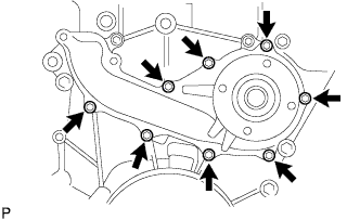
Remove the 8 bolts, water pump and gasket.
-
-
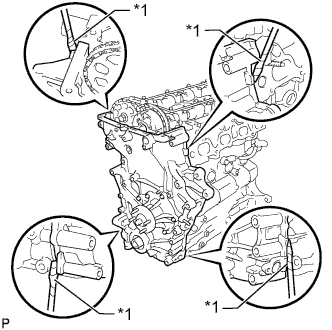
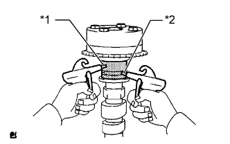
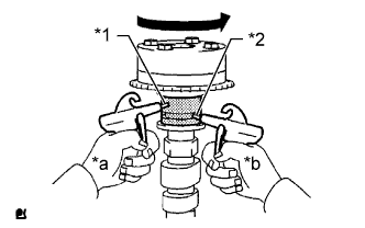
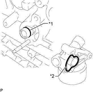
REMOVE TIMING CHAIN COVER OIL SEAL
-
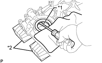
Text in Illustration *1 Protective Tape *2 Wooden Block Place the timing chain cover on wooden blocks.
-
Using a screwdriver pry out the oil seal.
Tech Tips
Tape the screwdriver tip before use.
-
-
REMOVE OIL PUMP RELIEF VALVE
-
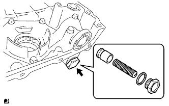
Using a 27 mm socket wrench, remove the relief valve plug and gasket.
-
Remove the valve spring and oil pump relief valve.
-
-
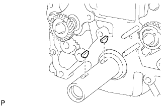
SET NO. 1 CYLINDER TO TDC/COMPRESSION
-
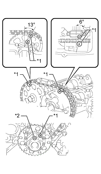
Text in Illustration *1 Timing Mark *2 Key Temporarily install the crankshaft pulley bolt.
-
Rotate the crankshaft clockwise so that the timing marks on the crankshaft timing gear and camshaft timing gears are as shown in the illustration.
Tech Tips
If the timing marks do not align, rotate the crankshaft clockwise again and align the timing marks.
-
Remove the crankshaft pulley bolt.
-
-
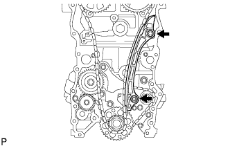
REMOVE TIMING CHAIN GUIDE
-
Remove the 2 bolts, chain guide and O-ring.
-
-
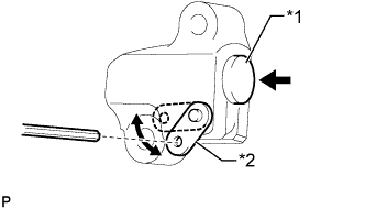
REMOVE NO. 1 CHAIN TENSIONER ASSEMBLY
Note
-
When the chain tensioner is removed, do not rotate the crankshaft.
-
When the chain is removed and the camshaft needs to be rotated, rotate the crankshaft 90° to the right.
-
Move the stopper plate upward to release the lock and push the plunger deep into the tensioner.
-
Move the stopper plate downward to set the lock and insert a 3.0 mm (0.118 in.) diameter bar into the stopper plate hole.
-
Text in Illustration *1 Plunger *2 Stopper Plate Remove the bolt, nut, chain tensioner and gasket.
-
-
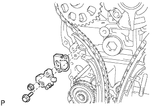
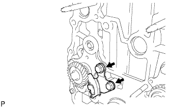
REMOVE CHAIN TENSIONER SLIPPER
-
Remove the bolt and tensioner slipper.
-
-
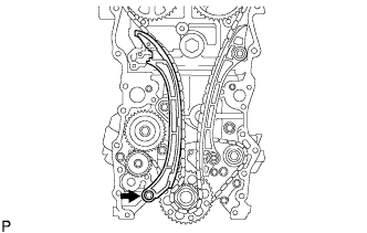
REMOVE NO. 1 CHAIN VIBRATION DAMPER
-
Remove the 2 bolts and vibration damper.
-
-
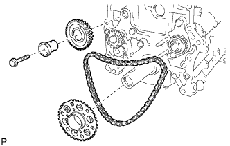
REMOVE CHAIN SUB-ASSEMBLY
-
REMOVE CRANKSHAFT TIMING GEAR
-
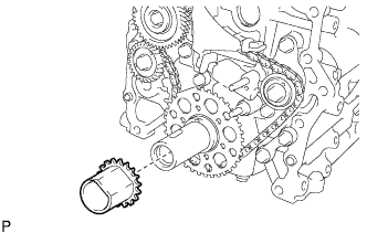
Remove the crankshaft timing gear from the crankshaft.
-
-
REMOVE CAMSHAFT BEARING CAP
-
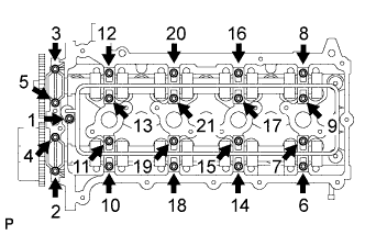
Uniformly loosen and remove the 21 bearing cap bolts in the sequence shown in the illustration.
Note
Uniformly loosen the bolts while keeping the camshaft level.
-
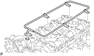
Remove the oil delivery pipe and O-ring from the bearing caps.
-
Remove the 9 bearing caps.
Tech Tips
Arrange the removed parts in the correct order.
-
-
REMOVE CAMSHAFT
-
REMOVE NO. 2 CAMSHAFT
-
REMOVE NO. 1 VALVE ROCKER ARM SUB-ASSEMBLY
-
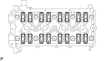
Remove the 16 valve rocker arms from the cylinder head.
Tech Tips
Arrange the removed parts in the correct order.
-
-
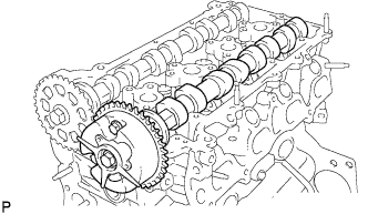
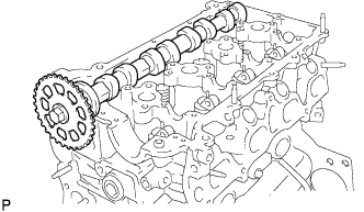
REMOVE CAMSHAFT TIMING SPROCKET
-
Mount the camshaft in a vise and remove the sprocket bolt and camshaft timing sprocket.
Note
Do not damage the camshaft.
-
-
INSPECT CAMSHAFT TIMING GEAR ASSEMBLY
-
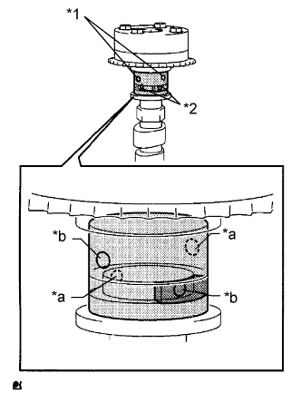
Text in Illustration *1 Retard Side Path *2 Advance Side Path *a Open *b Close 
Rubber Piece 
Vinyl Tape Check the lock of the camshaft timing gear.
-
Mount the camshaft in a vise and confirm that the camshaft timing gear is locked.
Note
Do not damage the camshaft.
-
-
Release the lock pin.
-
Cover the 4 oil paths of the cam journal with vinyl tape as shown in the illustration.
Tech Tips
2 advance side paths are provided in the groove of the camshaft. Plug one of the paths with a rubber piece.
-
Break through the tape over the advance side path, and then break through the tape over the retard side path on the opposite side of the hole over the advance side path as shown in the illustration.
-
Text in Illustration *1 Retard Side Path *2 Advance Side Path Apply compressed air at approximately 200 kPa (2.0 kgf/cm2, 28 psi) to the two paths accessible through the holes in the tape.
CAUTION:
Some oil splashing will occur. Cover the paths with a piece of cloth.
-
Text in Illustration *1 Retard Side Path *2 Advance Side Path *a Decompress *b Hold Pressure Check that the camshaft timing gear revolves in the advance direction when reducing the air pressure applied to the retard side path.
OK Gear rotates in the advance direction. Tech Tips
This operation releases the lock pin which holds the timing gear in the most retarded position.
-
When the camshaft timing gear reaches the most advanced position, release the air pressure from the retard side path and advance side path in that order.
Note
Do not release the air pressure from the advance side path first. The gear may abruptly shift in the retard direction and break the lock pin.
-
-
Check for smooth rotation.
-
Rotate the camshaft timing gear within its movable range several times, but do not turn it to the most retarded position. Check that the gear rotates smoothly.
CAUTION:
Do not use air pressure to perform the smooth operation check.
-
-
Check the lock in the most retarded position.
-
Confirm that the camshaft timing gear becomes locked at the most retarded position.
-
-
-
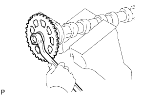
REMOVE CAMSHAFT TIMING GEAR ASSEMBLY
-
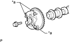
Text in Illustration *a Do Not Remove Remove the flange bolt and camshaft timing gear.
Note
-
Be sure not to remove the other 3 bolts.
-
If planning to reuse the gear, be sure to release the straight pin lock before installing the gear.
-
-
-
REMOVE CYLINDER HEAD SUB-ASSEMBLY
-
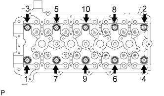
Uniformly loosen the 10 bolts in the sequence shown in the illustration. Remove the 10 cylinder head bolts and plate washers.
Note
-
Be careful not to drop the washers into the cylinder head.
-
Head warpage or cracking could result from removing the bolts in the wrong order.
-
-
-
REMOVE CYLINDER HEAD GASKET
-
Remove the cylinder head gasket from the cylinder block.
-
-
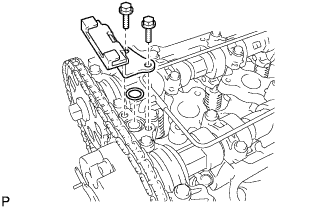
REMOVE NO. 2 CHAIN VIBRATION DAMPER
-
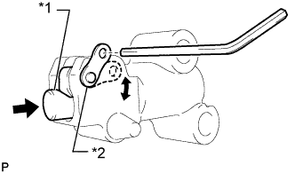
Text in Illustration *1 Plunger *2 Stopper Plate Move the stopper plate downward to release the lock and push the plunger deep into the tensioner.
-
Move the stopper plate upward to set the lock and insert a hexagon wrench into the stopper plate hole.
-
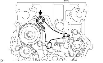
Remove the bolt and chain vibration damper.
-
-
REMOVE NO. 3 CHAIN VIBRATION DAMPER
-
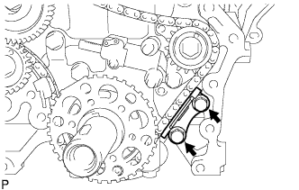
Remove the 2 bolts and chain vibration damper.
-
-
REMOVE NO. 2 CHAIN TENSIONER ASSEMBLY
-
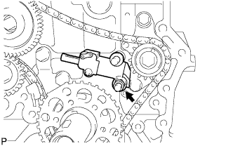
Remove the hexagon wrench from the tensioner assembly.
-
Remove the nut and chain tensioner assembly.
-
-
REMOVE NO. 2 CHAIN SUB-ASSEMBLY
-
Remove the bolt, balance shaft drive gear shaft and balance shaft drive gear.
-
Remove the crankshaft timing sprocket and chain.
-
-
REMOVE NO. 4 CHAIN VIBRATION DAMPER
-
Remove the 2 bolts and vibration damper.
-
-
REMOVE CRANKSHAFT PULLEY SET KEY
-
Remove the 2 pulley set keys from the crankshaft.
-
-
REMOVE OIL FILTER SUB-ASSEMBLY
-
Using SST, remove the oil filter.
- SST
- 09228-07501
-
-
REMOVE OIL FILTER BRACKET SUB-ASSEMBLY
-
Remove the 2 bolts and nut from the oil filter bracket.
-
Remove the 2 screw plugs and 2 gaskets from the oil filter bracket.
-
Text in Illustration *1 O-Ring *2 Oil Filter Bracket Gasket Remove the oil filter bracket gasket and O-ring.
-
Using a hexagon wrench, remove the oil filter bracket union.
-
-
REMOVE NO. 1 TAPER SCREW PLUG
-
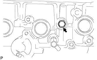
Remove the taper screw plug from the cylinder block.
-
-
REMOVE ENGINE REAR OIL SEAL RETAINER
-
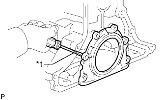
Text in Illustration *1 Protective Tape Remove the 6 bolts.
-
Using a screwdriver, pry out the oil seal retainer.
Tech Tips
Tape the screwdriver tip before use.
-
-
REMOVE ENGINE REAR OIL SEAL
-
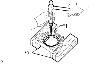
Text in Illustration *1 Protective Tape *2 Wooden Blocks Place the oil seal retainer on wooden blocks.
-
Using a screwdriver and hammer, tap out the oil seal.
Tech Tips
Tape the screwdriver tip before use.
-
-
REMOVE VALVE STEM CAP
-
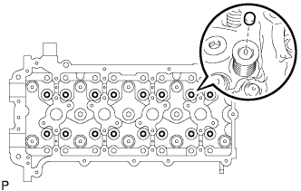
Remove the valve stem caps from the cylinder head.
Tech Tips
Arrange the removed parts in the correct order.
-
-
REMOVE VALVE LASH ADJUSTER ASSEMBLY
Note
-
Keep the lash adjuster free from dirt and foreign objects.
-
Only use clean engine oil.
-
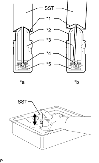
Text in Illustration *1 Taper Part *2 Plunger *3 Low Pressure Chamber *4 Check Ball *5 High Pressure Chamber *a CORRECT *b INCORRECT Place the lash adjuster into a container full of new engine oil.
-
Insert the tip of SST into the lash adjuster plunger and use the tip to press down on the check ball inside the plunger.
- SST
- 09276-75010
-
Squeeze SST and the lash adjuster together to move the plunger up and down 5 to 6 times.
-
Check the movement of the plunger and bleed air.
OK Plunger moves up and down. Note
When bleeding high-pressure air from the compression chamber, make sure that the tip of SST is actually pressing the check ball as shown in the illustration. If the check ball is not pressed, air will not bleed.
-
After bleeding the air, remove SST. Then try to quickly and firmly press the plunger with your fingers.
OK Plunger can be pressed 3 times. If the plunger can still be compressed after pressing it 3 times, replace the valve lash adjuster with a new one.
-
-
REMOVE OIL CONTROL VALVE FILTER
-
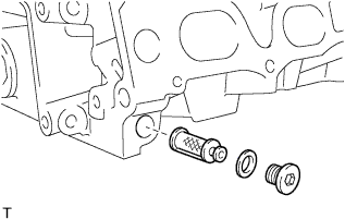
Using an 8 mm hexagon wrench, remove the screw plug.
-
Remove the oil control valve filter and gasket.
-