CYLINDER HEAD GASKET REMOVAL

-
REMOVE ENGINE ASSEMBLY
-
Remove the engine assembly Click here.
-
-
REMOVE NO. 1 EXHAUST MANIFOLD HEAT INSULATOR
-
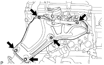
Remove the 5 bolts and No. 1 exhaust manifold heat insulator.
Tech Tips
-
It is only necessary to move the No. 1 exhaust manifold heat insulator so that the intake pipe can be removed in a later step.
-
It is not possible to fully remove the No. 1 exhaust manifold heat insulator in this step.
-
-
-
REMOVE NO. 4 INTAKE PIPE
-
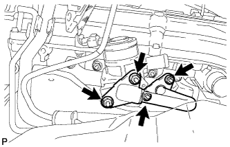
Remove the 4 nuts, No. 4 intake pipe and 2 gaskets.
Note
Be careful not to damage the installation surface of the gaskets.
-
-
REMOVE AIR SWITCHING VALVE ASSEMBLY
-
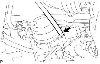
w/ Manifold Absolute Pressure Sensor:
Disconnect the vacuum hose.
-
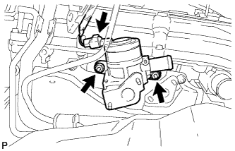
Disconnect the connector.
-
Remove the 2 nuts and air switching valve.
-
Remove the No. 1 exhaust manifold heat insulator.
-
-
REMOVE EXHAUST MANIFOLD
-
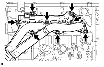
Remove the 8 nuts and exhaust manifold.
-
Remove the gasket.
-
-
REMOVE TIMING CHAIN COVER SUB-ASSEMBLY
-
Remove the timing chain cover sub-assembly Click here.
-
-
SET NO. 1 CYLINDER TO TDC/COMPRESSION
-
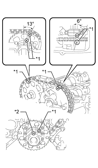
Text in Illustration *1 Timing Mark *2 Key Temporarily install the crankshaft pulley bolt.
-
Rotate the crankshaft clockwise so that the timing marks on the crankshaft timing gear and camshaft timing gears are as shown in the illustration.
Tech Tips
If the timing marks do not align, rotate the crankshaft clockwise again and align the timing marks.
-
Remove the crankshaft pulley bolt.
-
-
REMOVE TIMING CHAIN GUIDE
-
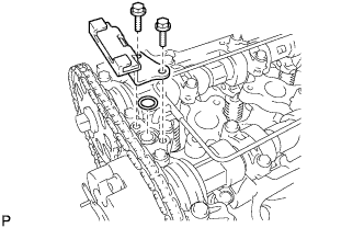
Remove the 2 bolts, chain guide and O-ring.
-
-
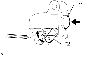
REMOVE NO. 1 CHAIN TENSIONER ASSEMBLY
Note
-
When the chain tensioner is removed, do not rotate the crankshaft.
-
When the chain is removed and the camshaft needs to be rotated, rotate the crankshaft 90° to the right.
-
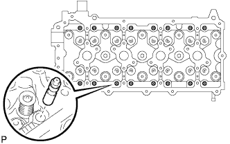
Move the stopper plate upward to release the lock and push the plunger deep into the tensioner.
-
Move the stopper plate downward to set the lock and insert a 3.0 mm (0.118 in.) diameter bar into the stopper plate hole.
-
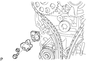
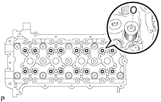
Text in Illustration *1 Plunger *2 Stopper Plate Remove the bolt, nut, chain tensioner and gasket.
-
-
REMOVE CHAIN TENSIONER SLIPPER
-
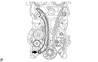
Remove the bolt and tensioner slipper.
-
-
REMOVE NO. 1 CHAIN VIBRATION DAMPER
-
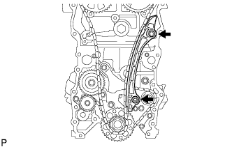
Remove the 2 bolts and vibration damper.
-
-
REMOVE CHAIN SUB-ASSEMBLY
-
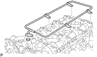
REMOVE CAMSHAFT BEARING CAP
-
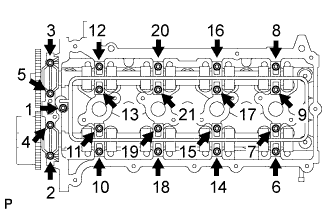
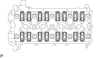
Uniformly loosen and remove the 21 bearing cap bolts in the sequence shown in the illustration.
Note
Uniformly loosen the bolts while keeping the camshaft level.
-
Remove the oil delivery pipe and O-ring from the bearing caps.
-
Remove the 9 bearing caps.
Tech Tips
Arrange the removed parts in the correct order.
-
-
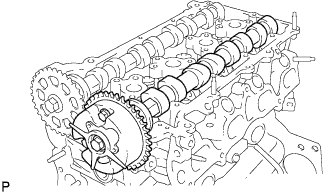
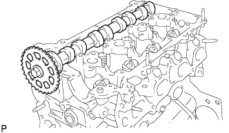
REMOVE CAMSHAFT
-
REMOVE NO. 2 CAMSHAFT
-
REMOVE NO. 1 VALVE ROCKER ARM SUB-ASSEMBLY
-
Remove the 16 valve rocker arms from the cylinder head.
Tech Tips
Arrange the removed parts in the correct order.
-
-
REMOVE VALVE LASH ADJUSTER ASSEMBLY
-
Remove the 16 valve lash adjusters from the cylinder head.
Tech Tips
Arrange the removed parts in the correct order.
-
-
REMOVE VALVE STEM CAP
-
Remove the valve stem caps from the cylinder head.
Tech Tips
Arrange the removed parts in the correct order.
-
-
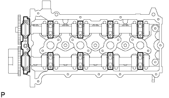
REMOVE CYLINDER HEAD SUB-ASSEMBLY
-
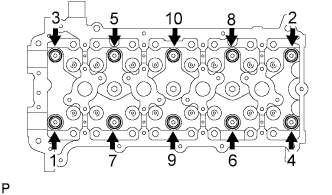
Uniformly loosen the 10 bolts in the sequence shown in the illustration. Remove the 10 cylinder head bolts and plate washers.
Note
-
Be careful not to drop the washers into the cylinder head.
-
Head warpage or cracking could result from removing the bolts in the wrong order.
-
-
-
REMOVE CYLINDER HEAD GASKET
-
Remove the cylinder head gasket from the cylinder block.
-
-
INSPECT CYLINDER HEAD SET BOLT
-
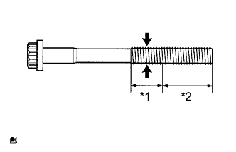
Text in Illustration *1 Measuring area *2 Distance Using a vernier caliper, measure the diameter of the most elongated threads in the measuring area.
Standard outside diameter 10.76 to 10.97 mm (0.424 to 0.432 in.) Minimum outside diameter 10.40 mm (0.409 in.) Distance 30 mm (1.18 in.) If a visual check reveals no excessively thin areas, check the center of the measuring area (see illustration) and find the area that has the smallest diameter.
If the diameter is less than the minimum, replace the cylinder head bolt.
-
-
INSPECT CYLINDER HEAD SUB-ASSEMBLY
-
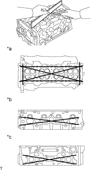
Text in Illustration *a Cylinder Head Lower Side *b Intake Manifold Side *c Exhaust Manifold Side Using a precision straightedge and feeler gauge, measure the warpage of the surfaces that contact the cylinder block and manifolds.
Maximum warpage 0.05 mm (0.00197 in.) If the warpage is more than the maximum, replace the cylinder head.
-
Using a dye penetrant, check the intake ports, exhaust ports and cylinder head surface for cracks.
If cracked, replace the cylinder head.
-