CAMSHAFT INSTALLATION

-
INSTALL CAMSHAFT TIMING GEAR ASSEMBLY
-
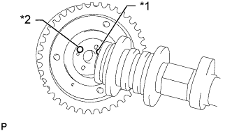
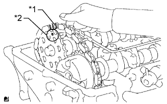
Text in Illustration *1 Straight Pin *2 Pin Hole Align the pin hole and straight pin and install the camshaft timing gear to the camshaft.
-
Lightly press the gear against the camshaft and turn the gear. Push further at the position where the pin enters the groove.
-
Check that there is no gap between the flange of the gear and the camshaft.
-
With the camshaft timing gear fixed in place, install the flange bolt.
- Torque:
- 78 N*m { 795 kgf*cm, 58 ft.*lbf }
-
Check that the camshaft timing gear can move in the retard direction and becomes locked at the most retarded position.
-
-
INSTALL VALVE LASH ADJUSTER ASSEMBLY
-
Inspect each valve lash adjuster before installing it Click here.
-
Install the 16 valve lash adjusters to the cylinder head.
Note
Install each lash adjuster to the same place it was removed from.
-
-
INSTALL NO. 1 VALVE ROCKER ARM SUB-ASSEMBLY
-
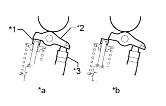
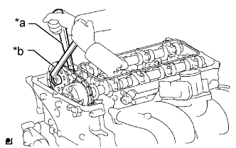
Text in Illustration *1 Valve Stem Cap *2 Valve Rocker Arm *3 Valve Lash Adjuster *a CORRECT *b INCORRECT Apply clean engine oil to the valve lash adjuster tips and valve stem cap surfaces.
-
Install the 16 valve rocker arms as shown in the illustration.
Note
Install each valve rocker arm to the same place it was removed from.
-
-
INSTALL CAMSHAFT
-
Apply clean engine oil to the camshaft cams and cylinder head journals.
-
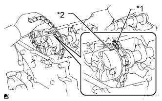
Install the timing chain to the camshaft timing gear with the painted mark of the link aligned with the timing mark of the camshaft timing gear.
Text in Illustration *1 Paint Mark *2 Timing Mark -
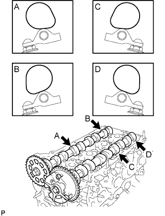
Text in Illustration *1 Valve Stem Cap *2 Valve Rocker Arm *3 Valve Lash Adjuster *a CORRECT *b INCORRECT Position the 2 camshafts as shown in the illustration.
Note
-
Align the paint mark and timing mark before positioning the camshaft.
-
Before and after positioning the camshaft and No. 2 camshaft, check that the rocker arm is firmly set on the lash adjuster.
-
-
Temporarily install the No. 1 camshaft bearing cap.
-
Check the proper location of each camshaft bearing cap and install each one.
-
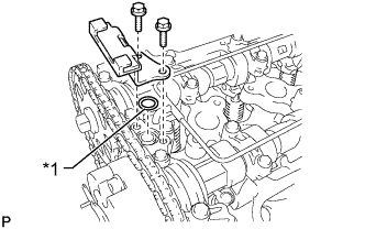
Text in Illustration *1 O-Ring Install a new O-ring to the No. 1 camshaft bearing cap.
-
Temporarily install the oil delivery pipe.
-
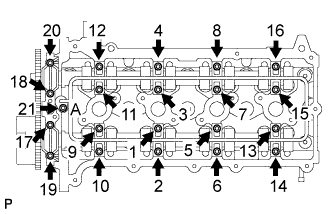
Install the 21 bolts and tighten them in the order shown in the illustration.
- Torque:
- for bolt A
- 12 N*m { 122 kgf*cm, 9 ft.*lbf }
- except bolt A
- 16 N*m { 158 kgf*cm, 11 ft.*lbf }
-
-
INSTALL CAMSHAFT TIMING SPROCKET
-
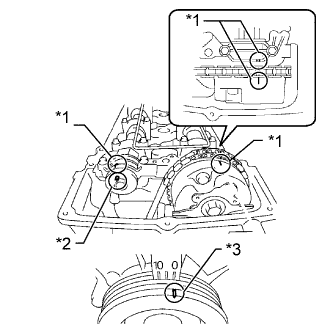
Text in Illustration *1 Timing Mark *2 Knock Pin *3 Groove Rotate the camshaft so that the camshaft timing mark and No. 2 camshaft knock pin are as shown in the illustration.
-
Turn the crankshaft pulley and align its groove with the "0" timing mark of the timing chain cover.
-
Text in Illustration *1 Paint Mark *2 Timing Mark Install the timing chain to the camshaft timing sprocket with the paint mark aligned with the timing marks on the camshaft timing sprocket.
-
Align the No. 2 camshaft knock pin and camshaft timing sprocket pin hole. Then install the camshaft timing sprocket to the No. 2 camshaft.
Note
If the knock pin and pin hole are difficult to align, slightly rotate the No. 2 camshaft back and forth using the hexagonal part of the camshaft. Then attempt alignment again.
-
Text in Illustration *a Hold *b Tighten Hold the camshaft with a wrench and tighten the sprocket bolt.
- Torque:
- 78 N*m { 795 kgf*cm, 58 ft.*lbf }
-
Remove the hexagon wrench from the chain tensioner.
-
Apply adhesive to 2 or 3 threads of the straight screw plug.
Adhesive Toyota Genuine Adhesive 1324, Three Bond 1324 or equivalent Note
Remove any oil from the bolt hole.
-
Using a 10 mm socket hexagon wrench, install the straight screw plug.
- Torque:
- 17 N*m { 169 kgf*cm, 12 ft.*lbf }
-
-
INSTALL TIMING CHAIN GUIDE
-
Text in Illustration *1 O-Ring Install a new O-ring to the camshaft bearing cap.
-
Install the timing chain guide with the 2 bolts.
- Torque:
- 10 N*m { 102 kgf*cm, 7 ft.*lbf }
-
-
INSTALL CYLINDER HEAD COVER SUB-ASSEMBLY
-
Install 2 new cover gaskets to the head cover.
-
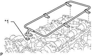
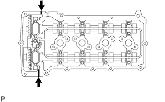
Apply seal packing to the places shown in the illustration.
Seal packing Toyota Genuine Seal Packing Black, Three Bond 1207B or equivalent Seal packing diameter 4.0 mm (0.157 in.) Text in Illustration 
Seal Packing Note
-
Remove any oil from the contact surface.
-
Install the head cover within 3 minutes after applying seal packing.
-
Do not start the engine for at least 4 hours after the installation.
-
-
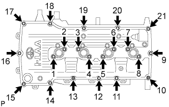
Temporarily install the head cover with the 19 bolts and 2 nuts.
-
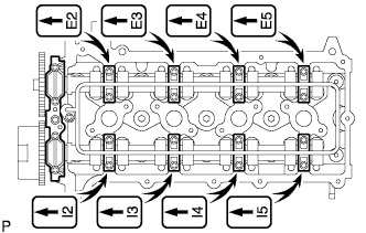
Uniformly tighten the 19 bolts and 2 nuts in the order shown in the illustration.
- Torque:
- 9.0 N*m { 92 kgf*cm, 80 in.*lbf }
-
In numerical order, confirm that the bolts labeled 1 to 8 are tightened to the specified torque. Tighten the bolts as necessary.
-
-
INSTALL CAMSHAFT POSITION SENSOR
-
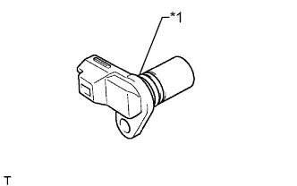
Text in Illustration *1 O-Ring Apply a light coat of engine oil to the O-ring of the camshaft position sensor.
-
Install the camshaft position sensor with the bolt.
- Torque:
- 8.5 N*m { 87 kgf*cm, 75 in.*lbf }
Note
Make sure that the O-ring is not cracked or jammed when installing.
-
Connect the camshaft position sensor connector.
-
-
INSTALL IGNITION COIL ASSEMBLY
-
Install the 4 ignition coils with the 4 bolts.
- Torque:
- 9.0 N*m { 92 kgf*cm, 80 in.*lbf }
-
Connect the 4 ignition coil connectors.
-
-
INSTALL FAN SHROUD
-
Install the fan pulley to the water pump.
-
Place the shroud together with the coupling fan between the radiator and engine.
Note
Be careful not to damage the radiator core.
-
Temporarily install the fluid coupling fan to the water pump with the 4 nuts. Tighten the nuts as much as possible by hand.
-
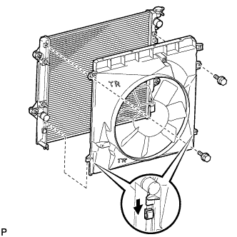
Attach the claws of the shroud to the radiator as shown in the illustration.
-
Install the shroud with the 2 bolts.
- Torque:
- 5.0 N*m { 51 kgf*cm, 44 in.*lbf }
-
Install the fan and generator V-belt Click here.
-
Tighten the 4 nuts of the fluid coupling fan.
- Torque:
- 25 N*m { 255 kgf*cm, 18 ft.*lbf }
-
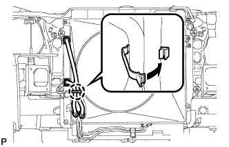
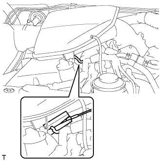
Attach the claw to close the flexible hose clamp as shown in the illustration.
-
-
INSTALL RADIATOR RESERVOIR
-
Install the radiator reservoir with the 3 bolts.
- Torque:
- 5.0 N*m { 51 kgf*cm, 44 in.*lbf }
-
Connect the reservoir hose to the radiator.
-
-
INSTALL INTAKE AIR CONNECTOR
-
Install the intake air connector with the 3 bolts.
- Torque:
- 8.0 N*m { 82 kgf*cm, 71 in.*lbf }
-
Tighten the hose clamp.
- Torque:
- 5.0 N*m { 51 kgf*cm, 44 in.*lbf }
-
Connect the vacuum hose.
-
Attach the wire harness clamp.
-
Connect the No. 2 ventilation hose.
-
w/ Manifold absolute pressure sensor:
-
Connect the vacuum hose.
-
Attach the 2 clamps.
-
Connect the air pressure sensor connector.
-
-
-
INSTALL AIR CLEANER CAP SUB-ASSEMBLY
-
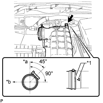
Text in Illustration *1 Matchmark *a Upper Side *b Front Install the air cleaner hose, align its matchmark with the matchmark of the air cleaner cap as shown in the illustration.
-
Tighten the hose clamp.
- Torque:
- 5.0 N*m { 51 kgf*cm, 44 in.*lbf }
-
Attach the 4 clamps.
-
Install the ground wire and clamp with the bolt.
- Torque:
- 8.5 N*m { 87 kgf*cm, 75 in.*lbf }
-
Connect the mass air flow meter connector and attach the 3 clamps.
-
-
CONNECT CABLE TO NEGATIVE BATTERY TERMINAL
Note
When disconnecting the cable, some systems need to be initialized after the cable is reconnected Click here.
-
ADD ENGINE OIL
-
Clean and install the oil drain plug and a new gasket.
- Torque:
- 38 N*m { 382 kgf*cm, 28 ft.*lbf }
-
Add fresh engine oil.
Standard Oil Grade Oil Grade Oil Viscosity (SAE) API grade SL "energy-conserving", SM "energy-conserving", SN "resource-conserving" or ILSAC multigrade engine oil
-
0W-20
-
5W-20
-
5W-30
-
10W-30
API grade SL, SM or SN multigrade engine oil
-
15W-40
-
20W-50
Standard Capacity Item Specified Condition Drain and refill without oil filter change 5.0 liters (5.3 US qts, 4.4 Imp. qts) Drain and refill with oil filter change 5.7 liters (6.0 US qts, 5.0 Imp. qts) Dry fill 6.1 liters (6.4 US qts, 5.4 Imp. qts) -
-
Install the oil filler cap.
-
-
INSPECT FOR OIL LEAK
-
Start the engine. Make sure that there are no oil leaks from the areas that were worked on.
-
-
INSPECT ENGINE OIL LEVEL
-
Warm up the engine, stop the engine and wait 5 minutes.
-
Check that the oil level is between the dipstick low level mark and full level mark.
If the level is low, check for leakage and add oil up to the full level mark.
Note
Do not fill engine oil above the full level mark.
-
-
INSPECT IGNITION TIMING
-
Warm up and stop the engine.
-
When using an intelligent tester:
-
Connect the intelligent tester to the DLC3.
-
Start the engine and idle it.
-
Turn the intelligent tester on.
-
Enter the following menus: Powertrain / Engine and ECT / Data List / IGN Advance.
Standard ignition timing 5 to 15° BTDC @ idle Tech Tips
Refer to the intelligent tester operator's manual for further details.
Note
-
When checking the ignition timing, the transaxle should be in neutral or park.
-
Switch off all the accessories and the A/C before connecting the intelligent tester.
-
-
Check that the ignition timing advances immediately when the engine speed is increased.
-
Enter the following menus: Powertrain / Engine and ECT / Active Test / Connect the TC and TE1.
-
Monitor IGN Advance.
-
Perform the Active Test.
Standard ignition timing 3 to 7° BTDC @ idle Tech Tips
Refer to the intelligent tester operator's manual for further details.
Note
When checking the ignition timing, the transmission should be in neutral or park.
-
-
When not using the intelligent tester:
-
Loosen the hose clamp from the throttle body side.
-
Remove the 3 bolts and disconnect the intake air connector.
Tech Tips
Move the intake air connector so that the tester probe of a timing light can be connected to the wire of the ignition coil for the No. 1 cylinder.
-
Connect the tester probe of a timing light to the wire of the ignition coil connector for the No. 1 cylinder.
Note
Use a timing light that detects primary signals.
-
Connect the intake air connector.
Tech Tips
Return the parts to their original positions so that the engine can be started.
-
Start the engine and idle it.
-
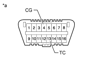
Text in Illustration *a Front view of DLC3 Using SST, connect terminals 13 (TC) and 4 (CG) of the DLC3.
- SST
- 09843-18040
Note
-
Confirm the terminal numbers before connecting them. Connecting the wrong terminals can damage the engine.
-
When checking the ignition timing, the shift lever should be in neutral or P.
-
Using the timing light, check the ignition timing.
Standard ignition timing 3 to 7° BTDC @ idle Note
-
Turn all the electrical systems and the A/C off.
-
When checking the ignition timing, the shift lever should be in neutral or P.
-
-
Remove SST from the DLC3.
-
Check the ignition timing.
Standard ignition timing 5 to 15° BTDC @ idle -
Check that the ignition timing advances immediately when the engine speed is increased.
-
Turn the ignition switch off.
-
Disconnect the timing light from the engine.
-
Connect the intake air connector with the 3 bolts.
- Torque:
- 8.0 N*m { 82 kgf*cm, 71 in.*lbf }
-
Tighten the hose clamp.
- Torque:
- 5.0 N*m { 51 kgf*cm, 44 in.*lbf }
-
-
-
INSPECT ENGINE IDLE SPEED
-
Warm up and stop the engine.
-
When using the intelligent tester:
-
Connect the intelligent tester to the DLC3.
-
Start the engine and idle it.
-
Turn the intelligent tester on.
-
Enter the following menus: Powertrain / Engine and ECT / Data List / Engine Speed.
Standard idle speed 600 to 700 rpm Tech Tips
Refer to the intelligent tester operator's manual for further details.
Note
-
Turn all the electrical systems and the A/C off.
-
When checking the idling speed, the shift lever should be in neutral or P.
-
-
Turn the ignition switch off.
-
Disconnect the intelligent tester from the DLC3.
-
-
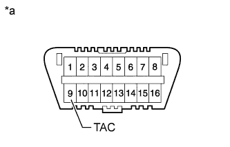
Text in Illustration *a Front view of DLC3 When not using the intelligent tester:
-
Using SST, connect a tachometer probe to terminal 9 (TAC) of the DLC3.
- SST
- 09843-18040
Note
-
Confirm the terminal numbers before connecting them. Connecting the wrong terminals can damage the engine.
-
Turn all the electrical systems and the A/C off.
-
When checking the idling speed, the shift lever should be in neutral or P.
-
Check the idle speed.
Standard idle speed 600 to 700 rpm -
Disconnect the tachometer probe from the DLC3.
-
-
If the engine speed is not as specified, update the idle speed control (ISC) learned value using either procedure 1 or procedure 2 below, and then check the engine speed again.
-
Procedure 1:
After completely warming up the engine, drive the vehicle at 30 km/h (19 mph) for 30 seconds or more and idle the engine for 30 seconds or more. Repeat this pattern 5 times or more.
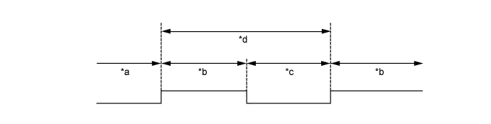
Text in Illustration *a Engine completely warmed up *b Vehicle being driven at 30 km/h (19 mph) *c Idling *d 1 time -
Procedure 2:
After completely warming up the engine, stop the engine and then idle it. Repeat this pattern 5 times or more.
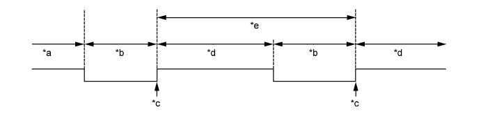
Text in Illustration *a Engine completely warmed up *b Engine stopped *c Engine started *d Idling *e 1 time - - Tech Tips
-
Be sure to idle the engine for 150 seconds or more for each time the pattern is repeated.
-
If the engine speed is not as specified after performing the procedure above, inspect the idle speed control system as it is malfunctioning.
-
-
-
-
INSTALL UPPER RADIATOR SUPPORT SEAL
-
Install the upper radiator support seal with the 13 clips.
-
-
INSTALL NO. 1 ENGINE UNDER COVER SUB-ASSEMBLY
-
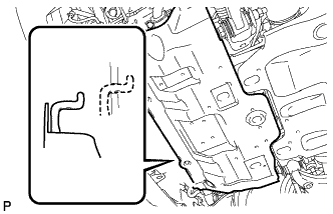
Hook the engine under cover to the vehicle body as shown in the illustration.
-
Install the 4 bolts.
- Torque:
- 29 N*m { 296 kgf*cm, 21 ft.*lbf }
-
-
INSTALL FRONT BUMPER COVER LOWER
-
Install the front bumper cover lower with the 5 bolts and clip.
- Torque:
- 8.0 N*m { 82 kgf*cm, 71 in.*lbf }
-