CAMSHAFT REMOVAL

-
DISCONNECT CABLE FROM NEGATIVE BATTERY TERMINAL
Note
-
After turning the ignition switch off, waiting time may be required before disconnecting the cable from the battery terminal. Therefore, make sure to read the disconnecting the cable from the battery terminal notice before proceeding with work Click here.
-
When disconnecting the cable, some systems need to be initialized after the cable is reconnected Click here.
-
-
REMOVE FRONT BUMPER COVER LOWER
-
Remove the clip, 5 bolts and front bumper cover lower.
-
-
REMOVE NO. 1 ENGINE UNDER COVER SUB-ASSEMBLY
-
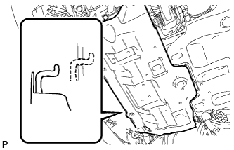
Remove the 4 bolts.
-
Unhook the engine under cover from the vehicle body as shown in the illustration.
-
-
REMOVE UPPER RADIATOR SUPPORT SEAL
-
Remove the 13 clips and upper radiator support seal.
-
-
DRAIN ENGINE OIL
-
Remove the oil filler cap.
-
Remove the oil drain plug and gasket, and drain the oil into a container.
-
-
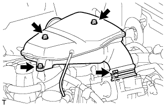
REMOVE AIR CLEANER CAP SUB-ASSEMBLY
-
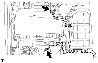
Detach the 3 clamps and disconnect the mass air flow meter connector.
-
Remove the bolt, detach the clamp and disconnect the ground wire.
-
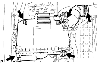
Detach the 4 clamps.
-
Loosen the hose clamp and remove the air cleaner cap.
-
-
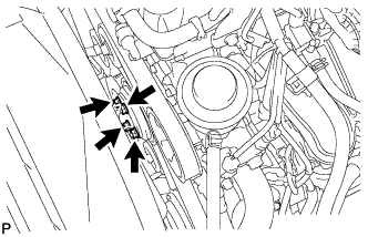
REMOVE INTAKE AIR CONNECTOR
-
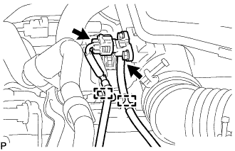
w/ Manifold absolute pressure sensor:
-
Disconnect the air pressure sensor connector.
-
Detach the 2 clamps.
-
Disconnect the vacuum hose.
-
-
Disconnect the No. 2 ventilation hose.
-
Detach the wire harness clamp.
-
Disconnect the vacuum hose.
-
Loosen the hose clamp.
-
Remove the 3 bolts and intake air connector.
-
-
REMOVE RADIATOR RESERVOIR
-
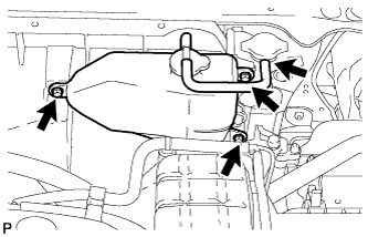
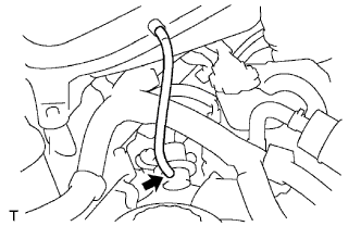
Disconnect the reservoir hose from the radiator.
-
Remove the 3 bolts and radiator reservoir.
-
-
REMOVE FAN SHROUD
-
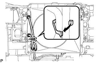
Detach the claw to open the flexible hose clamp.
-
Loosen the 4 nuts holding the fluid coupling fan.
-
Remove the fan and generator V-belt Click here.
-
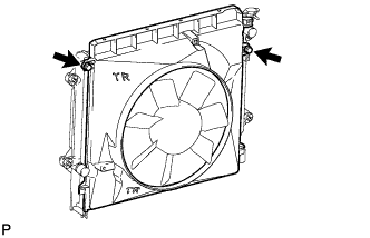
Remove the 2 bolts holding the fan shroud.
-
Remove the 4 nuts of the fluid coupling fan, and then remove the shroud together with the coupling fan.
Note
Be careful not to damage the radiator core.
-
-
REMOVE IGNITION COIL ASSEMBLY
-
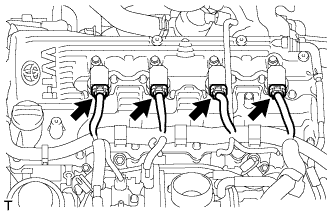
Disconnect the 4 ignition coil connectors.
-
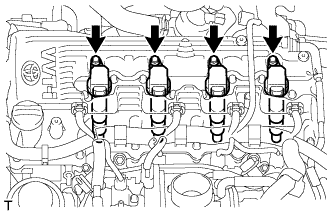
Remove the 4 bolts and 4 ignition coils.
-
-
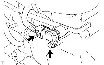
REMOVE CAMSHAFT POSITION SENSOR
-
Disconnect the camshaft position sensor connector.
-
Remove the bolt and camshaft position sensor.
-
-
REMOVE CYLINDER HEAD COVER SUB-ASSEMBLY
-
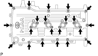
Remove the 19 bolts, 2 nuts, head cover and 2 gaskets.
-
-
REMOVE TIMING CHAIN GUIDE
-
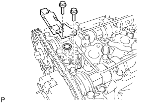
Remove the 2 bolts, chain guide and O-ring.
-
-
REMOVE CAMSHAFT TIMING SPROCKET
-
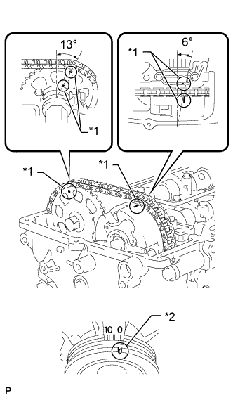
Turn the crankshaft pulley, and align its groove with the "0" timing mark of the timing chain cover.
-
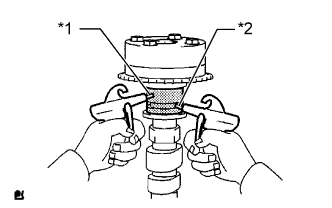
Check that the timing marks of the camshaft timing gear and sprocket are aligned with the timing marks of the No. 1 bearing cap as shown in the illustration.
Text in Illustration *1 Timing Mark *2 Groove Tech Tips
If the timing marks do not align, rotate the crankshaft clockwise again and align the timing marks.
-
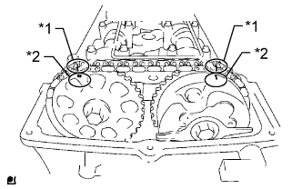
Text in Illustration *1 Paint Mark *2 Timing Mark Place paint marks on the timing chain, camshaft timing gear and sprocket.
-
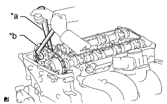
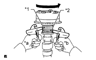
Text in Illustration *a Hold *b Loosen Hold the camshaft with a wrench and loosen the sprocket bolt.
Note
Be careful not to damage the oil delivery pipe.
-
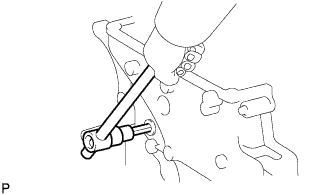
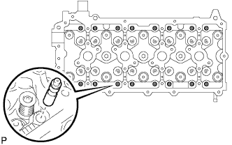
Using a 10 mm socket hexagon wrench, remove the straight screw plug.
-
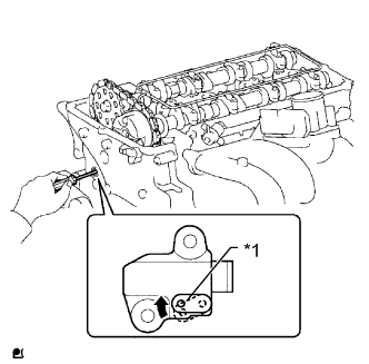
Text in Illustration *1 Stopper Plate Using a screwdriver, access the tensioner stopper plate through the chain tensioner service hole. Move the stopper plate upward to release the lock. Then hold the plate in that position as shown in the illustration.
Tech Tips
If the lock of the stopper plate is difficult to release, slightly rotate the hexagonal part of the camshaft to the left and right.
-
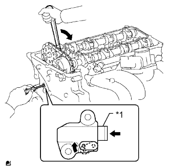
Text in Illustration *1 Plunger With the lock of the stopper plate released, slightly rotate the camshaft clockwise and keep it in that position.
Tech Tips
Rotating the camshaft clockwise will cause pressure to be applied to the tensioner plunger.
Note
Be careful not to damage the oil delivery pipe.
-
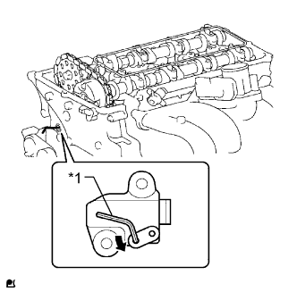
Text in Illustration *1 Hexagon Wrench Remove the screwdriver from the chain tensioner service hole. Move the stopper plate to the position shown in the illustration. Then insert a hexagon wrench into the hole.
Tech Tips
-
If the wrench cannot fit into the hole, slightly rotate the camshaft counterclockwise and then clockwise. Then insert the wrench.
-
To prevent the wrench from falling out, use tape to fix the wrench in place.
-
-
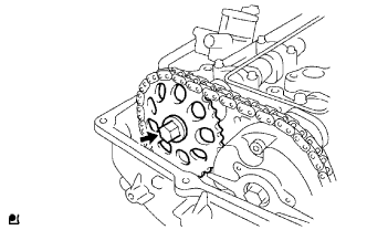
Remove the camshaft timing sprocket from the No. 2 camshaft.
-
-
REMOVE CAMSHAFT
-
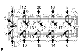
Uniformly loosen the 21 bearing cap bolts in several passes in the sequence shown in the illustration.
-
Remove the 9 bearing caps, oil delivery pipe, O-ring and No. 2 camshaft.
Note
-
Uniformly loosen the bolts while keeping the camshaft level.
-
Do not pry the camshaft with a tool or apply excessive force to it.
-
-
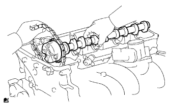
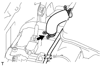
Remove the camshaft while holding the timing chain.
-
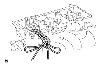
Secure the timing chain with a string as shown in the illustration.
Note
Be careful not to drop anything inside the timing chain cover.
-
-
REMOVE NO. 1 VALVE ROCKER ARM SUB-ASSEMBLY
-
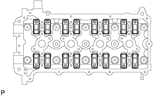
Remove the 16 valve rocker arms from the cylinder head.
Tech Tips
Arrange the removed parts in the correct order.
-
-
REMOVE VALVE LASH ADJUSTER ASSEMBLY
-
Remove the 16 valve lash adjusters from the cylinder head.
Tech Tips
Arrange the removed parts in the correct order.
-
-
REMOVE CAMSHAFT TIMING GEAR ASSEMBLY
-
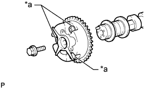
Text in Illustration *a Do Not Remove Remove the flange bolt and camshaft timing gear.
Note
-
Be sure not to remove the other 3 bolts.
-
If planning to reuse the gear, be sure to release the straight pin lock before installing the gear.
-
-
-
INSPECT VALVE LASH ADJUSTER ASSEMBLY
Note
-
Keep the lash adjuster free from dirt and foreign objects.
-
Only use clean engine oil.
-
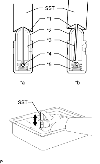
Text in Illustration *1 Taper Part *2 Plunger *3 Low Pressure Chamber *4 Check Ball *5 High Pressure Chamber *a CORRECT *b INCORRECT Place the lash adjuster into a container full of new engine oil.
-
Insert the tip of SST into the lash adjuster plunger and use the tip to press down on the check ball inside the plunger.
- SST
- 09276-75010
-
Squeeze SST and the lash adjuster together to move the plunger up and down 5 to 6 times.
-
Check the movement of the plunger and bleed air.
OK Plunger moves up and down. Note
When bleeding high-pressure air from the compression chamber, make sure that the tip of SST is actually pressing the check ball as shown in the illustration. If the check ball is not pressed, air will not bleed.
-
After bleeding the air, remove SST. Then try to quickly and firmly press the plunger with your fingers.
OK Plunger can be pressed 3 times. If the plunger can still be compressed after pressing it 3 times, replace the valve lash adjuster with a new one.
-
-
INSPECT CAMSHAFT TIMING GEAR ASSEMBLY
-
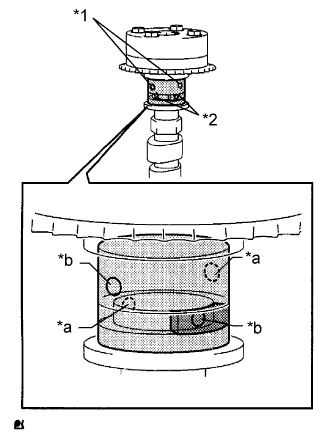
Text in Illustration *1 Retard Side Path *2 Advance Side Path *a Open *b Close 
Rubber Piece 
Vinyl Tape Check the lock of the camshaft timing gear.
-
Mount the camshaft in a vise and confirm that the camshaft timing gear is locked.
Note
Do not damage the camshaft.
-
-
Release the lock pin.
-
Cover the 4 oil paths of the cam journal with vinyl tape as shown in the illustration.
Tech Tips
2 advance side paths are provided in the groove of the camshaft. Plug one of the paths with a rubber piece.
-
Break through the tape over the advance side path, and then break through the tape over the retard side path on the opposite side of the hole over the advance side path as shown in the illustration.
-
Text in Illustration *1 Retard Side Path *2 Advance Side Path Apply compressed air at approximately 200 kPa (2.0 kgf/cm2, 28 psi) to the two paths accessible through the holes in the tape.
CAUTION:
Some oil splashing will occur. Cover the paths with a piece of cloth.
-
Text in Illustration *1 Retard Side Path *2 Advance Side Path *a Decompress *b Hold Pressure Check that the camshaft timing gear revolves in the advance direction when reducing the air pressure applied to the retard side path.
OK Gear rotates in the advance direction. Tech Tips
This operation releases the lock pin which holds the timing gear in the most retarded position.
-
When the camshaft timing gear reaches the most advanced position, release the air pressure from the retard side path and advance side path in that order.
Note
Do not release the air pressure from the advance side path first. The gear may abruptly shift in the retard direction and break the lock pin.
-
-
Check for smooth rotation.
-
Rotate the camshaft timing gear within its movable range several times, but do not turn it to the most retarded position. Check that the gear rotates smoothly.
CAUTION:
Do not use air pressure to perform the smooth operation check.
-
-
Check the lock in the most retarded position.
-
Confirm that the camshaft timing gear becomes locked at the most retarded position.
-
-